Projection optical system

a projection optical and optical system technology, applied in the field of projection optical systems, can solve problems such as poor image contrast, and achieve the effect of improving the contrast and resolution of the projected imag

Active Publication Date: 2007-02-27
CORETRONIC
View PDF3 Cites 0 Cited by
  • Summary
  • Abstract
  • Description
  • Claims
  • Application Information

AI Technical Summary

Benefits of technology

[0008]The objective of the present invention is to provide a projection optical system for fully shielding off the stray light to improve the contrast and the resolution of the projected image.
[0009]The other objective of the present invention is to provide a projection optical system capable of effectively dispersing the heat of the stray light to lower the temperature of the system.
[0010]In an embodiment, the projection optical system of the present invention comprises an illumination light source, a digital micromirror device (DMD), a projection lens, and a first block sheet. The illumination light source is used for providing an illumination light. The DMD comprises a plurality of micromirrors for separating the illumination light into a signal light, a first stray light, and a second stray light by varying, in accordance with a signal, the respective angles at which each micromirror reflects the illumination light shone thereon. The signal light passes through the projection lens and is further projected onto a screen. The first block sheet is disposed closely to the projection lens for shielding off the first stray light and the second stray light without shielding off the signal light. Since the first block sheet can fully shield off the first stray light and the second stray light, the contrast and the resolution of the projected image is improved.
[0012]Therefore, the projection optical system of the present invention can fully shield off the stray light by disposing the first block sheet at a specific position, such that the contrast and the resolution of the projected image is improved. Furthermore, the present invention utilizes the heat sink to disperse the heat of the stray light to lower the temperature of the system.

Problems solved by technology

However, the height of the block sheet 16 of the prior art can only fully shield off the second stray light 20 and cannot shield off the first stray light 18, so the first stray light 18 will directly be projected into the projection lens 12, causing worse contrast of the image.

Method used


Image

  • Projection optical system
  • Projection optical system
  • Projection optical system

Examples


Embodiment Construction

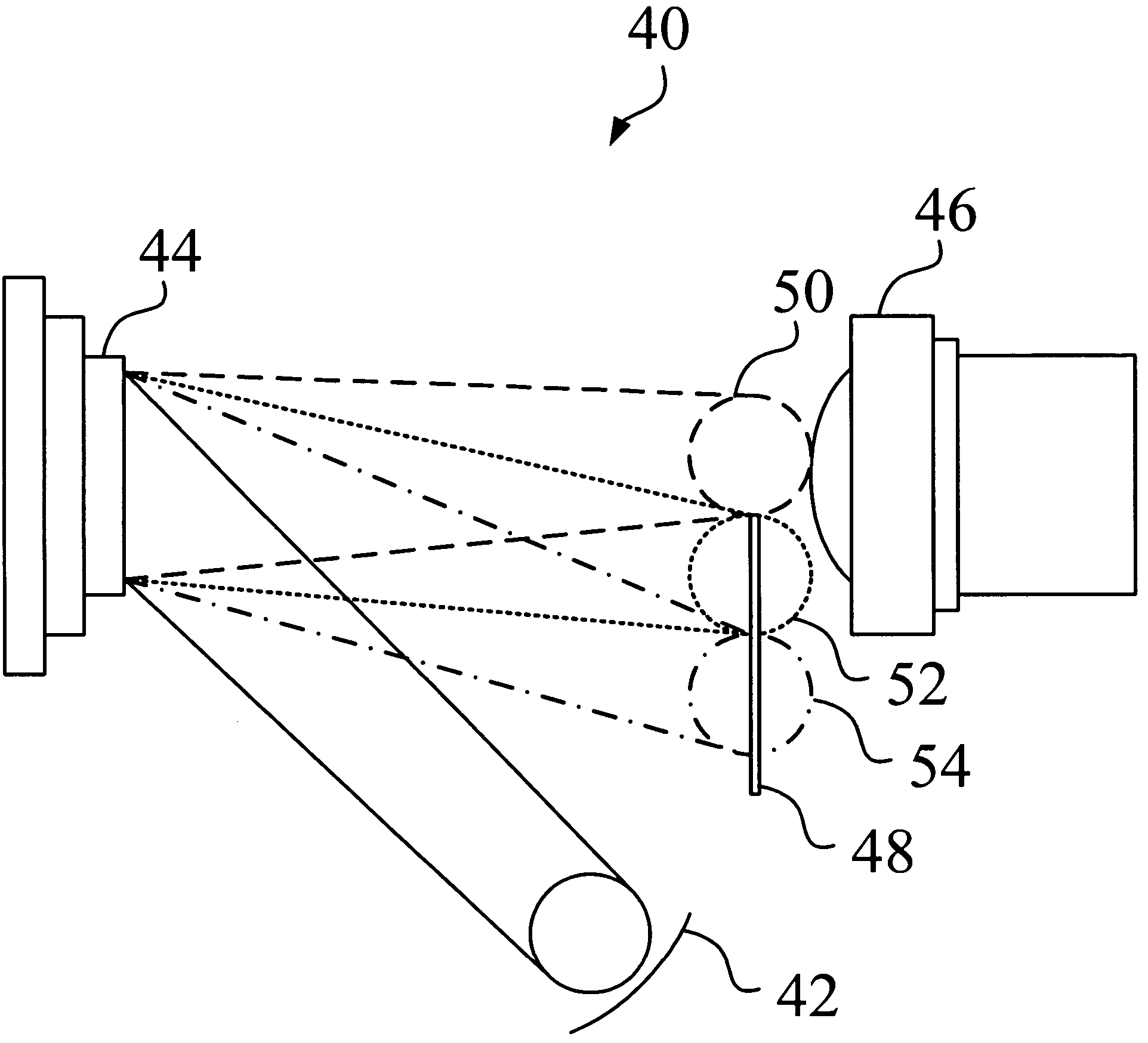
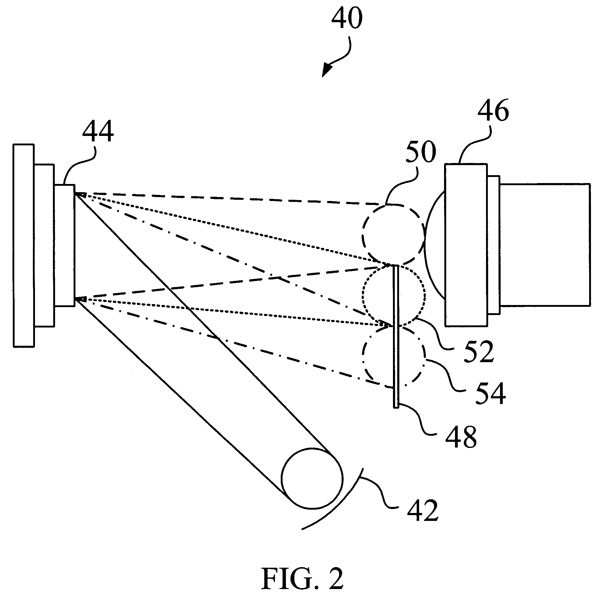
[0018]Referring to FIG. 2, FIG. 2 is a schematic diagram of the projection optical system 40 according to one embodiment of the present invention. To describe the figure more clearly, the lights shown in FIG. 2 are respectively marked with different lines. According to the present invention, the projection optical system 40 comprises an illumination light source 42, a digital micromirror device (DMD) 44, a projection lens 46 and a first block sheet 48. The illumination light source 42 is used for providing an illumination light.

[0019]The DMD 44 comprises a plurality of micromirrors for separating the illumination light into a signal light 50, a first stray light 52, and a second stray light 54 by varying, in accordance with a signal, the respective angles at which each micromirror reflects the illumination light shone thereon. When each of the micromirrors respectively rotates to +12 degree to be in an ON state, each micromirror reflects the illumination light shone thereon to gener...


PUM


Abstract

A projection optical system includes a light source, a digital micromirror device (DMD), a projection lens and a first block sheet. The light source provides an illumination light. The DMD includes a plurality of micromirrors, and the angles of each micromirrors are changed individually according to an input signal for separating the illumination light reflected from the micromirrors into a signal light, a first stray light and a second stray light. The signal light passes through the projection lens and is further projected onto a screen. The first block sheet is disposed closely to the projection lens to allow the first stray light and the second stray light to be fully shielded off by the first block sheet and thus not to reach the projection lens.

Description

BACKGROUND OF THE INVENTION[0001]1. Field of the Invention[0002]The present invention relates to a projection optical system, and more particular to a projection optical system capable of effectively eliminating stray light.[0003]2. Description of the Prior Art[0004]The digital micromirror device (DMD) is an image display device. The DMD is usually used in a conventional projection optical system for adjusting an illumination light from an illumination light source. The DMD comprises a plurality of micromirrors, and it is controlled by an inputted signal to rotate, so as to reflect the illumination light in three separate directions. Accordingly, the projection optical system can provide an image with high resolution.[0005]Referring to FIG. 1, FIG. 1 is a schematic diagram of the projection optical system 10 of the prior art. In the projection optical system 10, the DMD 14 comprises a plurality of micromirrors arranged in an array thereon. Each of the micromirrors is controlled by a...

Claims


Application Information

Patent Timeline
Patent Type & Authority Patents(United States)
IPC IPC(8): G02B9/00G02B21/14G02B26/08
CPCG02B27/0018H04N9/3197H04N9/3141H04N9/3111
Inventor CHEN, SHOU-CHIHHUANG, HUNG-CHIEH
Owner CORETRONIC
Why Eureka
Try Eureka