
Ceramic spindle coupling structure

a ceramic spindle and coupling technology, applied in the direction of branching pipes, liquid fuel engine components, non-positive displacement fluid engines, etc., can solve the problems of insufficient airflow, insufficient rotation speed, and insufficient airflow of air fans used in high-speed processors such as microprocessors that include metal spindles, so as to improve the coupling structure of ceramic spindles and reduce the cost. , the effect of increasing the friction for

Inactive Publication Date: 2007-02-27
ZIPPY TECH
View PDF5 Cites 7 Cited by
  • Summary
  • Abstract
  • Description
  • Claims
  • Application Information

AI Technical Summary

Benefits of technology

[0005]Therefore the primary object of the invention is to provide a simpler ceramic spindle coupling structure. A metal bushing with a tapered housing space is provided to form a tight coupling with a ceramic spindle so that embossing of the inner wall and outer surface of the metal bushing to increase the friction force is not necessary. Thereby cost may be reduced.

Problems solved by technology

The conventional air fans used on high speed processors such as microprocessors that include metal spindles encounter many problems such as the airflow is not sufficient to disperse the growing amount of heat being generated, rotation speed is not fast enough, etc.
Increasing the speed and airflow volume will result in shorter service life of the metal spindle.
However, test process during fabrication shows that there are still problems in the design of the ceramic spindle remained to be resolved.
The ceramic spindle generally has a smooth surface and a low friction coefficient, hence the centrifugal force occurred at high speed rotation of the fan tend to result in separation of the ceramic spindle from the air fan and incurs skid.
The embossing process is useless for the ceramic spindle since the ceramic spindle is very hard and rigid.
Even if the embossing process is finally done and successfully created a rough surface to the ceramic spindle, it would be a very time and cost consuming which is not economical.
Production cost is higher.

Method used


Image

  • Ceramic spindle coupling structure
  • Ceramic spindle coupling structure
  • Ceramic spindle coupling structure

Examples


Embodiment Construction

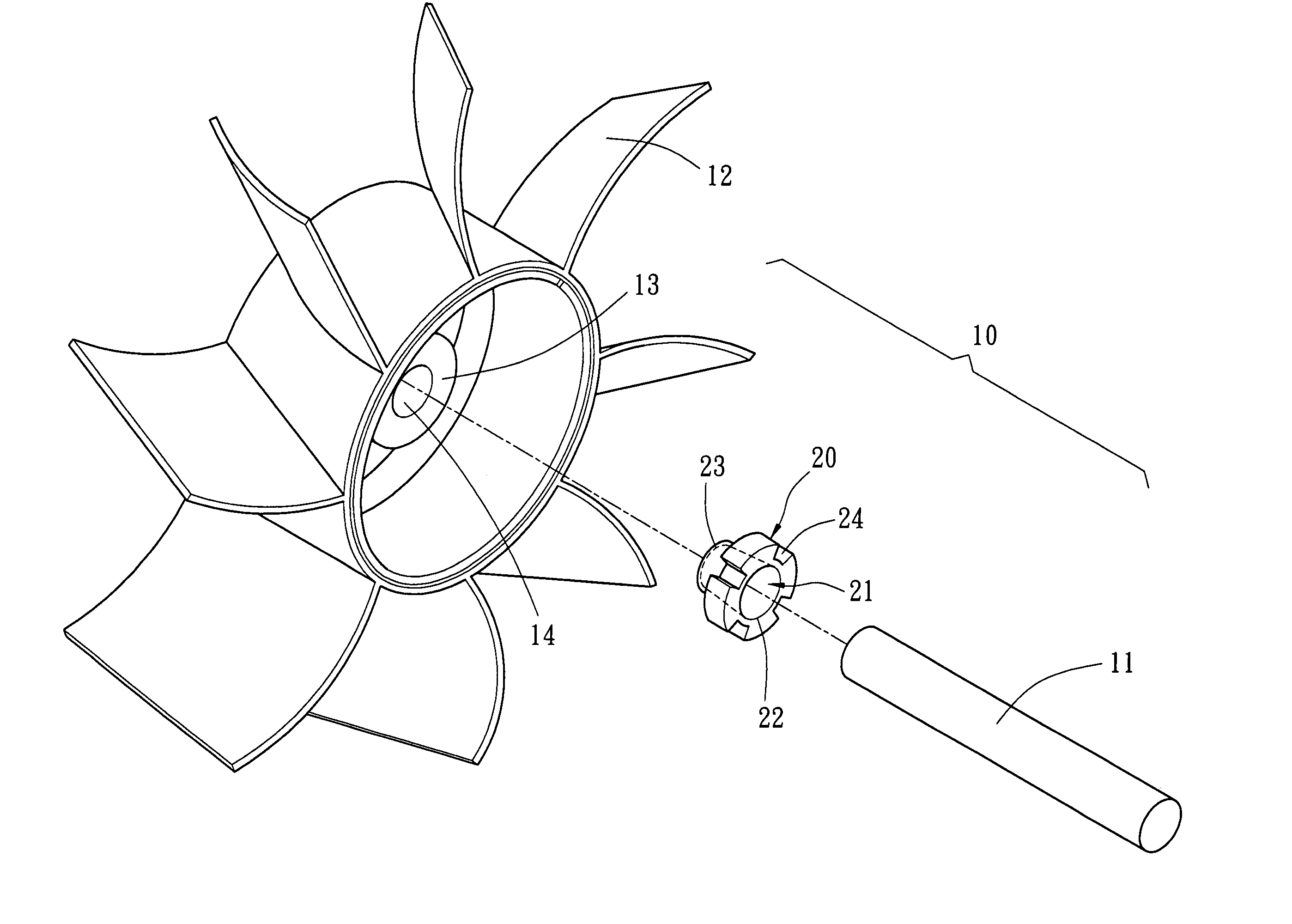
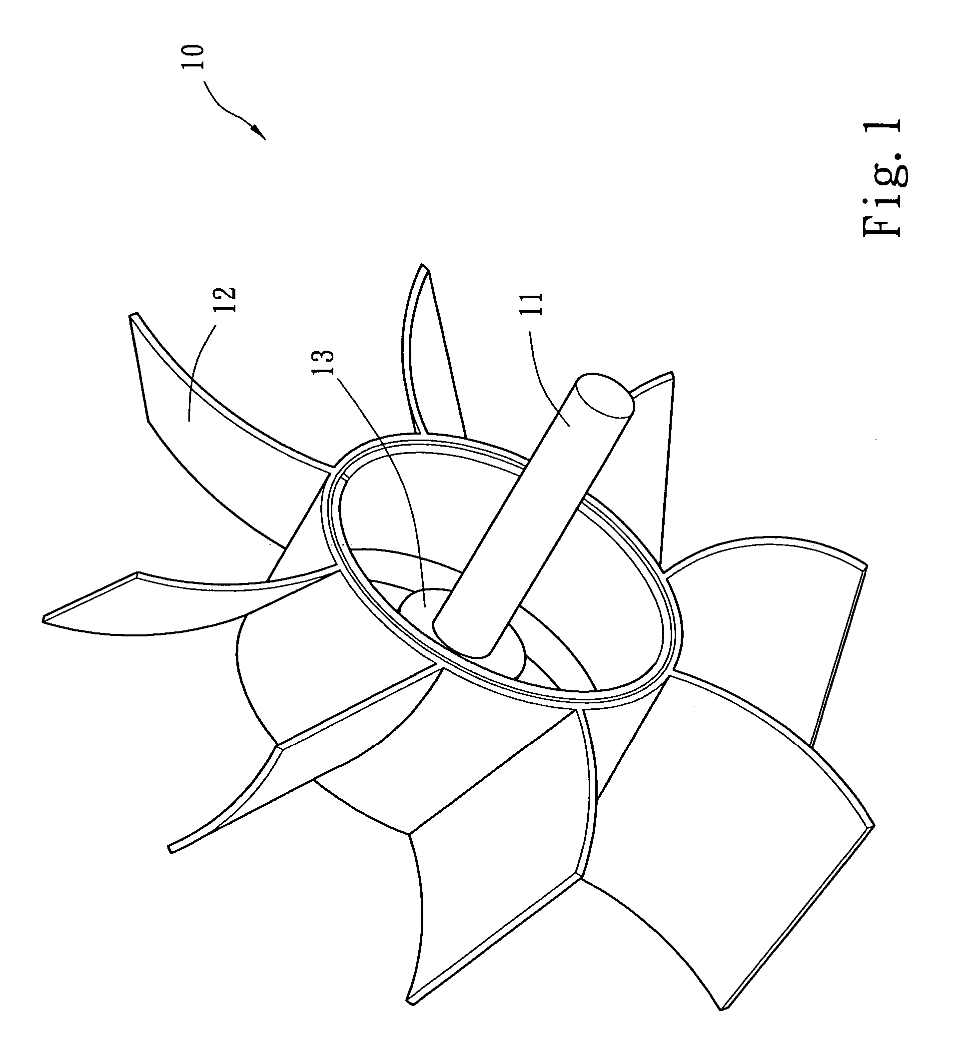
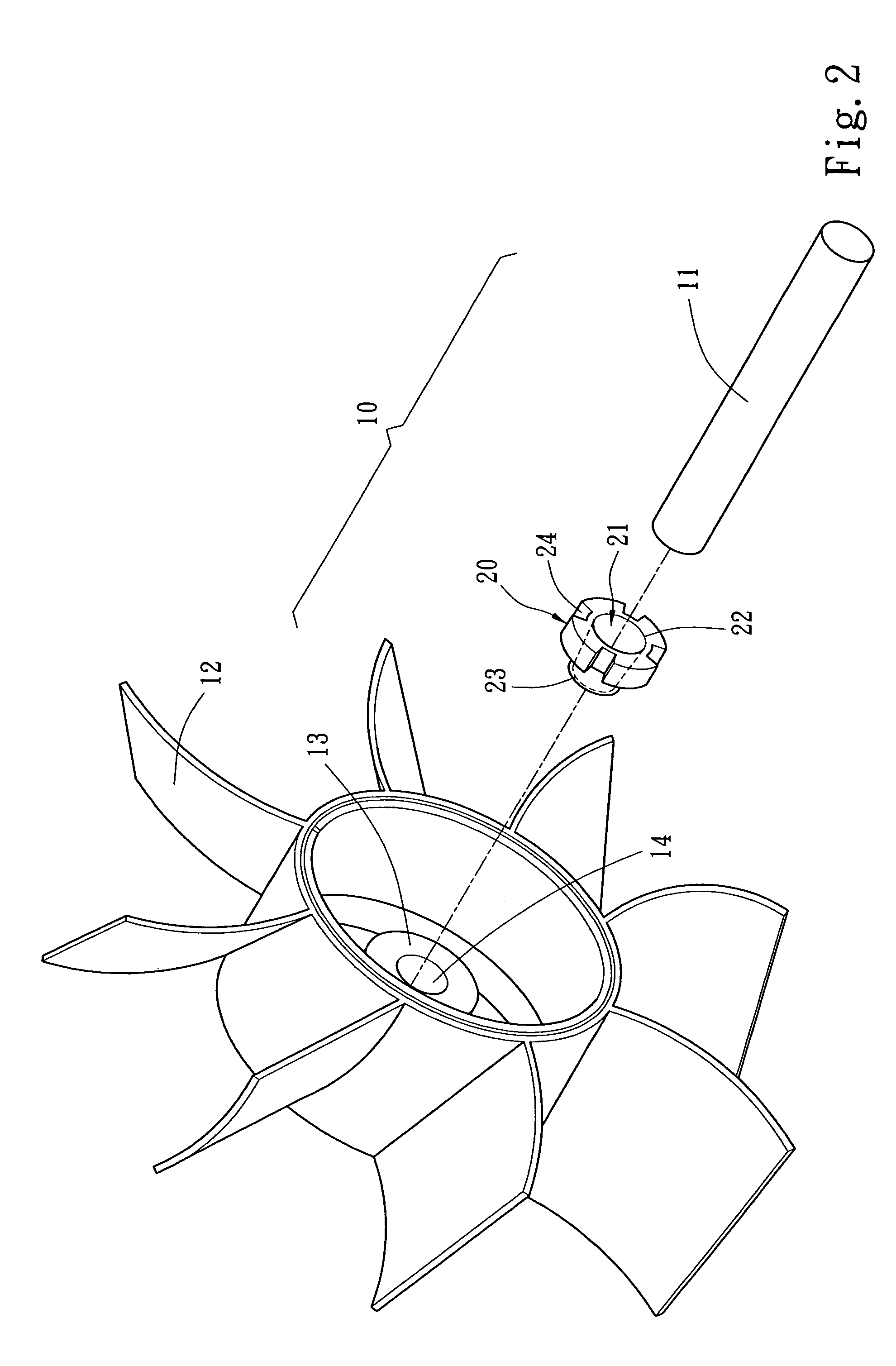
[0010]Please refer to FIGS. 1, 2 and 3, according to the invention an air fan 10 includes a ceramic spindle 11 and vanes 12. In order to increase the speed and airflow volume of the air fan 10, the ceramic spindle 11 is made from material that is hard and rigid, and can withstand wearing and high temperature. The ceramic spindle 11 generally has a hard and smooth surface. Hence a metal bushing 20 is provided as the fastening medium to couple the ceramic spindle 11 with the vanes 12.

[0011]Referring to FIGS. 1 and 2, the metal bushing 20 has a housing space 21 in the interior. The housing space 21 has an inlet 22 and a fastening section 23. The housing space 21 is tapered at the fastening section 23 from the inlet 22 so that the ceramic spindle 11 may be inserted from the inlet 22 and squeezed and held tightly at the fastening section 23 to form a secured coupling. The metal bushing 20 further has a coupling section 24 at one end corresponding to the inlet 22. The coupling section 24 ...


PUM

PropertyMeasurementUnit
diameteraaaaaaaaaa
outer diameteraaaaaaaaaa
inner diameteraaaaaaaaaa

Abstract

A ceramic spindle coupling structure includes a metal bushing which has a housing space that has an inlet and a tapered fastening section of a smaller diameter than the inlet to form a tight coupling with a ceramic spindle without embossing the ceramic spindle and the metal bushing.

Description

FIELD OF THE INVENTION[0001]The present invention relates to a ceramic spindle coupling structure and particularly to a structure for coupling a ceramic spindle with air fan vanes through a metal bushing.BACKGROUND OF THE INVENTION[0002]The conventional air fans used on high speed processors such as microprocessors that include metal spindles encounter many problems such as the airflow is not sufficient to disperse the growing amount of heat being generated, rotation speed is not fast enough, etc. Increasing the speed and airflow volume will result in shorter service life of the metal spindle. Therefore ceramic spindle has gradually replaced the metal spindle these days. The ceramic material is very hard and rigid, and can withstand wearing and high temperature. Thus the air fan rotation speed may increase to disperse heat as desired.[0003]However, test process during fabrication shows that there are still problems in the design of the ceramic spindle remained to be resolved. For in...

Claims


Application Information

Patent Timeline
Patent Type & Authority Patents(United States)
IPC IPC(8): B64C11/04F16D1/06
CPCF16D1/06F16D1/097F16D2001/062Y10T403/7051Y10T403/10Y10T403/3933Y10T403/3941Y10T403/4637Y10T403/7052
Inventor CHOU, CHIN-WEN
Owner ZIPPY TECH
Learn More