Qualitative diagnosis system and method

a technology of qualitative diagnosis and system measurement, applied in the direction of electric controllers, instruments, ignition automatic control, etc., can solve the problems of discontinuities in continuous physical system models, difficult to establish cause effect relations between individual component parameter changes and difficult to draw cause effect relations between individual component parameters and observed transients in system measurements

Inactive Publication Date: 2007-02-20
VANDERBILT UNIV
View PDF0 Cites 12 Cited by
  • Summary
  • Abstract
  • Description
  • Claims
  • Application Information

AI Technical Summary

Benefits of technology

[0018]Yet a further method is taught by a method of establishing a predicted future value by including the effect of negative loop structure feedback in a temporal causal graph representation of a system including a plurality of vertices in an algebraic loop. This method includes predicting an initial future value, establishing an initial order and a sufficient propagation order for root deviations, propagating time integral effects on each order from the initial order through the sufficient propagation order to establish adjustment variables, and refining the initial future value in accordance with the adjustment variables to establish the predicted future value. Establishing a sufficient propagation order includes selecting the lowest propagation order necessary to capture transients having a substantive impact on the accuracy of the representation. Propagating for this method includes establishing an entry point vertex; and examining a successor vertex for a valid feedback effect on the entry point vertex. The examining a successor vertex includes reviewing successor level derivates to establish successor derivative values when the successor level is in a feedback loop; checking the successor derivative values for conflicts based on the entry point vertex; modifying the successor level value in accordance with the derivative variable; and setting the adjustment successor level value.

Problems solved by technology

Typically the abstraction process creates lumped parameter models, which makes it hard to draw cause effect relation between individual component parameter changes and observed transients in the measurements.
Also, discontinuities may emerge in models of continuous physical systems as an artifact of abstracting physical phenomena that operate on a temporal or spatial scale much smaller than that of interest to the modeller.
As previously noted, this simplified models often produce lumped parameter representations that make it hard to establish cause effect relations between individual component parameters and observed transients in the system measurements.

Method used


Image

  • Qualitative diagnosis system and method
  • Qualitative diagnosis system and method
  • Qualitative diagnosis system and method

Examples


Embodiment Construction

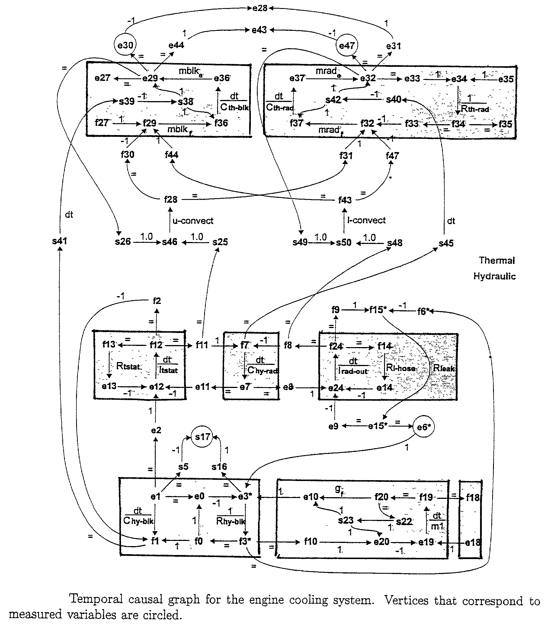
[0033]The present invention is based on TRANSCEND (trademark), which is a system for monitoring and diagnosis of complex dynamic systems using qualitative transient analysis methods to overcome the difficulties that arise in numerical processing, especially for nonlinear systems. The future behavior of hypothesized faults is predicted in the form of signatures, and analyzed by a progressive monitoring scheme. Thus, this provides a model based diagnosis system for fault detection and isolation of abrupt faults in engineered systems such as fast breeder reactors and automobile engines. It applies models of dynamic system behavior to obtain accurate predictions for measured transients and compares predictions with actual observations to distill the true cause for the faulty behavior. To successfully perform diagnosis, this system needs a dynamic model of the system.

[0034]A critical task in designing the model for fault detection and isolation (FDI) is to determine the bandwidth of the ...


PUM


Abstract

A system and method for predicting the behavior of a complex physical system with a qualitative analysis by correctly handling algebraic loops in physical system models for diagnosis applications. This approach recognizes the presence of negative feedback effects in loop structures and analyses these effects by tracking the entry point into the algebraic loop to resolve conflicting predictions.

Description

[0001]This application claims benefit of co-pending U.S. Patent Application Ser. No. 60 / 294,967 filed May 31, 2001, entitled “A Qualitative Diagnosis of Systems with Models that Includes a Class of Algebraic Loops” which is hereby incorporated by reference.[0002]A portion of the disclosure of this patent document contains material that is subject to copyright protection. The copyright owner has no objection to the facsimile reproduction by anyone of the patent document or the patent disclosure, as it appears in the Patent and Trademark office patent file or records, but otherwise reserves all copyright rights whatsoever.BACKGROUND OF THE INVENTION[0003]The present invention relates generally to predicting the behavior of a complex physical system with a qualitative analysis. More particularly, this invention pertains to improving the resolution of the prediction by correctly handling algebraic loops in physical system models for diagnosis applications. The prior art has recognized t...

Claims


Application Information

Patent Timeline
Patent Type & Authority Patents(United States)
IPC IPC(8): G01R15/00G05B11/01G05B15/00G06F17/50G06F19/00G06G7/48
CPCG05B23/0248G05B23/021
Inventor MOSTERMAN, PIETER J.MANDERS, ERIC J.BISWAS, GAUTAM
Owner VANDERBILT UNIV
Why Eureka
Try Eureka