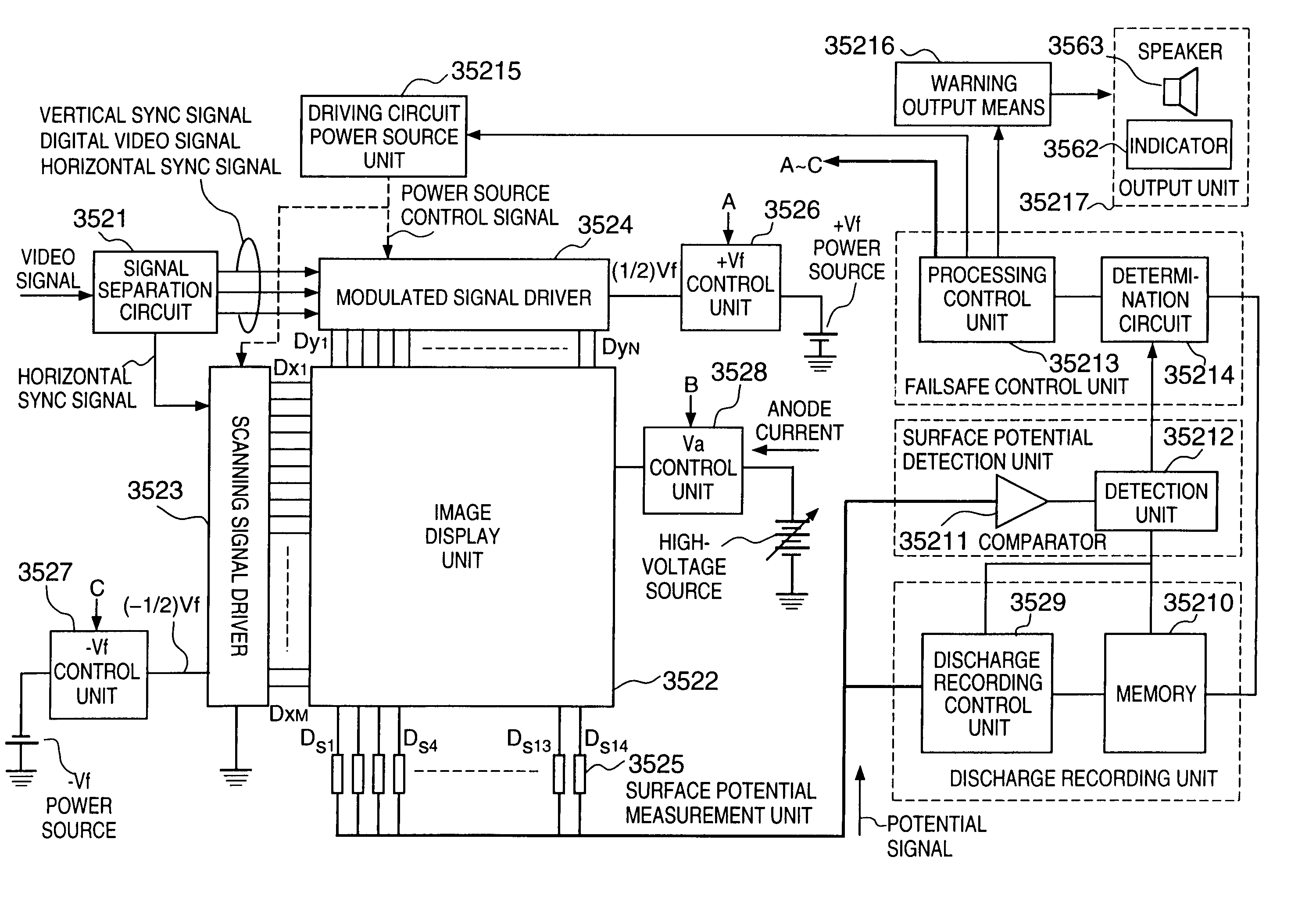
Image display apparatus and control method thereof
a technology of image display and control method, which is applied in the direction of instruments, discharge tubes, luminescent screen, etc., can solve the problems of low response speed of hot cathode device, high response speed of cold cathode device, and hardly arisen heat fusion of substra
- Summary
- Abstract
- Description
- Claims
- Application Information
AI Technical Summary
Benefits of technology
Problems solved by technology
Method used
Image
Examples
first embodiment
[First Embodiment]
[0117]As the first embodiment of the present invention, a display panel using an electron-emitting device and a driving circuit for the display panel will be described in detail. The display panel of the first embodiment has the same structure as shown in FIG. 31, and a detailed description thereof will be omitted.
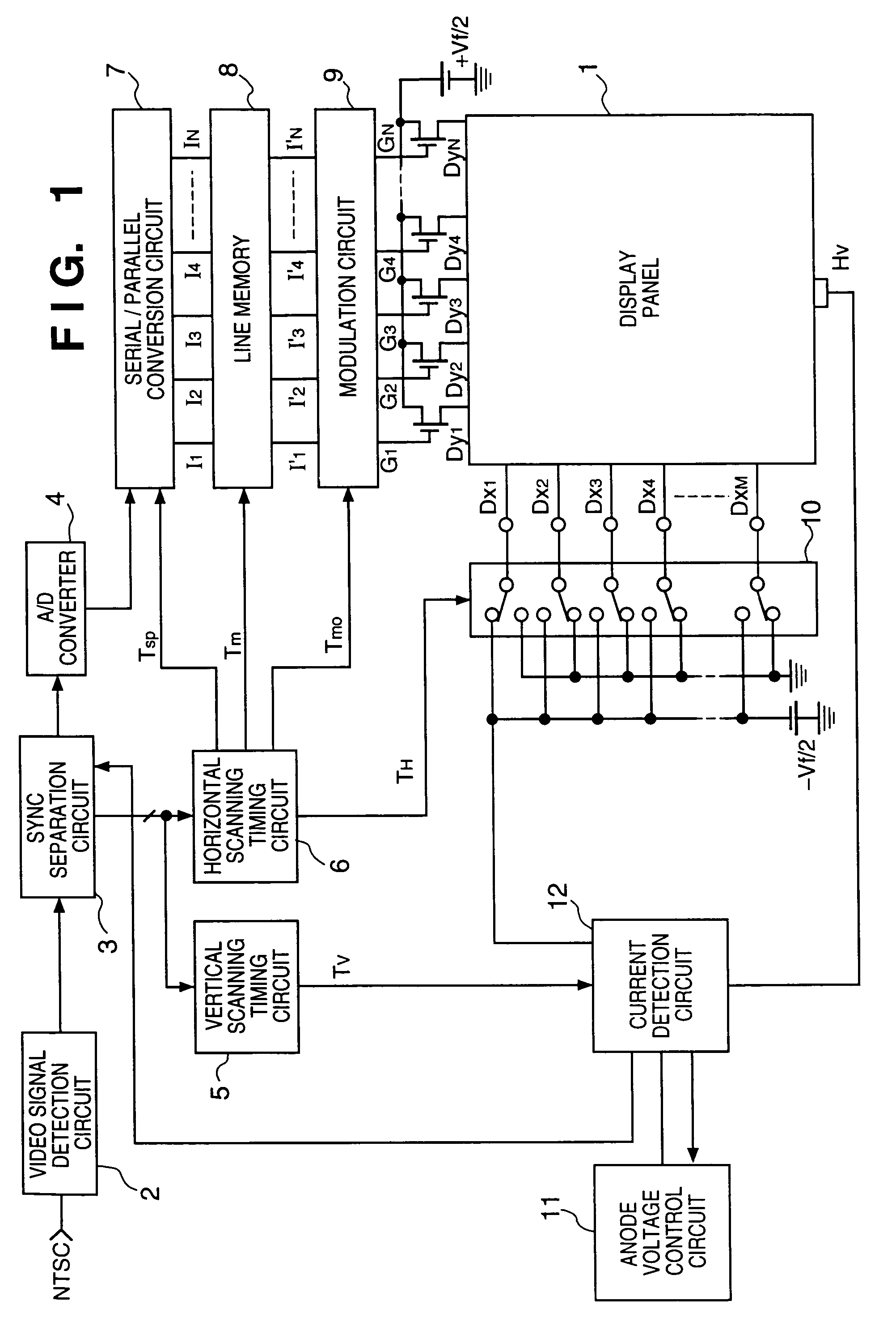
[0118]FIG. 1 is a block diagram showing the arrangement of a driving circuit for the display panel of an image display apparatus according to the first embodiment.
[0119]In FIG. 1, reference numeral 1 denotes a display panel using a cold cathode device (electron-emitting device: to be described in detail later). An external video signal (e.g., an NTSC signal) is input to a video signal detection circuit 2 for detecting a video signal, and an output from the video signal detection circuit 2 is input to a sync separation circuit 3 for separating and outputting a video signal and horizontal and vertical sync signals.
[0120]The video signal separated by the syn...
second embodiment
[Second Embodiment]
[0135]FIG. 3 is a perspective view of a display panel 1a according to the second embodiment of the present invention where part of the display panel 1a is removed for showing the internal structure of the panel.
[0136]The display panel of the second embodiment has almost the same structure as the display panel shown in FIG. 31 except that a fluorescent substance 3118 and a metal back 3119 are uniformly divided on a face plate 3117, as represented by fluorescent plates 13 in FIG. 3. In addition, the second embodiment uses a substrate 3111 as a rear plate without using any rear plate 3115. The same reference numerals as in FIG. 31 denote the same parts, and a description thereof will be omitted.
[0137]The fluorescent plates 13 are used to individually detect local variations in spacer current inside the display panel 1a, and enable detection of a partial anode current or the like, compared to the first embodiment. The second embodiment employs 10 divided fluorescent p...
third embodiment
[Third Embodiment]
[0146]FIG. 5 is a perspective view of a display panel 1b according to the third embodiment of the present invention. In FIG. 5, part of the panel is removed for showing the internal structure of the panel.
[0147]In the third embodiment, dummy spacers 16 are formed from the same material by the same manufacturing method as spacers 3120 on a dummy wiring 17 formed along the column wiring in the display panel of the second embodiment shown in FIG. 3. Similar to the second embodiment, the dummy spacers 16 respectively correspond to a plurality of fluorescent plates 13 each including a fluorescent substance and metal back. The dummy spacers 16 are equal in number to 10 divided fluorescent plates 13.
[0148]The dummy wiring 17 is formed at a position independently of row and column wirings connecting electron-emitting devices 3112 laid out in a matrix.
[0149]The first and second embodiments detect a current value flowing through the spacer itself in the display panel, wherea...
PUM
 Abstract
Description
Claims
Application Information
 - R&D
- Intellectual Property
- Life Sciences
- Materials
- Tech Scout
- Unparalleled Data Quality
- Higher Quality Content
- 60% Fewer Hallucinations
Browse by: Latest US Patents, China's latest patents, Technical Efficacy Thesaurus, Application Domain, Technology Topic, Popular Technical Reports.
© 2025 PatSnap. All rights reserved.Legal|Privacy policy|Modern Slavery Act Transparency Statement|Sitemap|About US| Contact US: help@patsnap.com


