
RFID reader utilizing an analog to digital converter for data acquisition and power monitoring functions

a technology of rfid reader and converter, which is applied in the field of rfid system construction and operation, can solve the problems of limiting the practicality of the reader for universal applications, finite life, and complex circuitry of the reader circui

Active Publication Date: 2007-02-20
ASSA ABLOY AB
View PDF14 Cites 47 Cited by
  • Summary
  • Abstract
  • Description
  • Claims
  • Application Information

AI Technical Summary

Benefits of technology

The present invention is a reader for an RFID system that includes a signal generator for transmitting and receiving signals. The reader has a transmitting antenna and a receiving antenna, which can be the same or different. The reader also has a transmitting tuning capacitor and a receiving tuning capacitor to tune the antennas to different frequencies. The reader includes a microcontroller for conditioning the received signal and a sample and hold circuit for isolating points on the detection signal. The receiver electronics include a resistor divider section and a peak detector section for reducing the voltage value of the received signal. The reader can be used in various applications such as RFID cards and RFID readers.

Problems solved by technology

As a rule, the circuitry of the reader is more extensive and complex than the circuitry of the transponder because the reader requires a higher degree of functionality relative to the transponder, particularly in the case of a passive transponder.
Although the design of the reader disclosed in the '263 patent realizes some economies of size and cost over the prior art by integrating a plurality of electronic components and their functionalities into the microcontroller of the reader, the use of an external multi-stage band pass amplifier limits the practicality of the reader for universal applications.
A battery, however, has a finite life necessitating replacement of the battery in the reader at the end of its useful life, which is both costly and time consuming.
The ring signals are transmitted from a reader antenna and the ring signals propagate into the space surrounding the reader, but are insufficient to power operation of any transponders residing in the surrounding space.

Method used


Image

  • RFID reader utilizing an analog to digital converter for data acquisition and power monitoring functions
  • RFID reader utilizing an analog to digital converter for data acquisition and power monitoring functions
  • RFID reader utilizing an analog to digital converter for data acquisition and power monitoring functions

Examples


Embodiment Construction

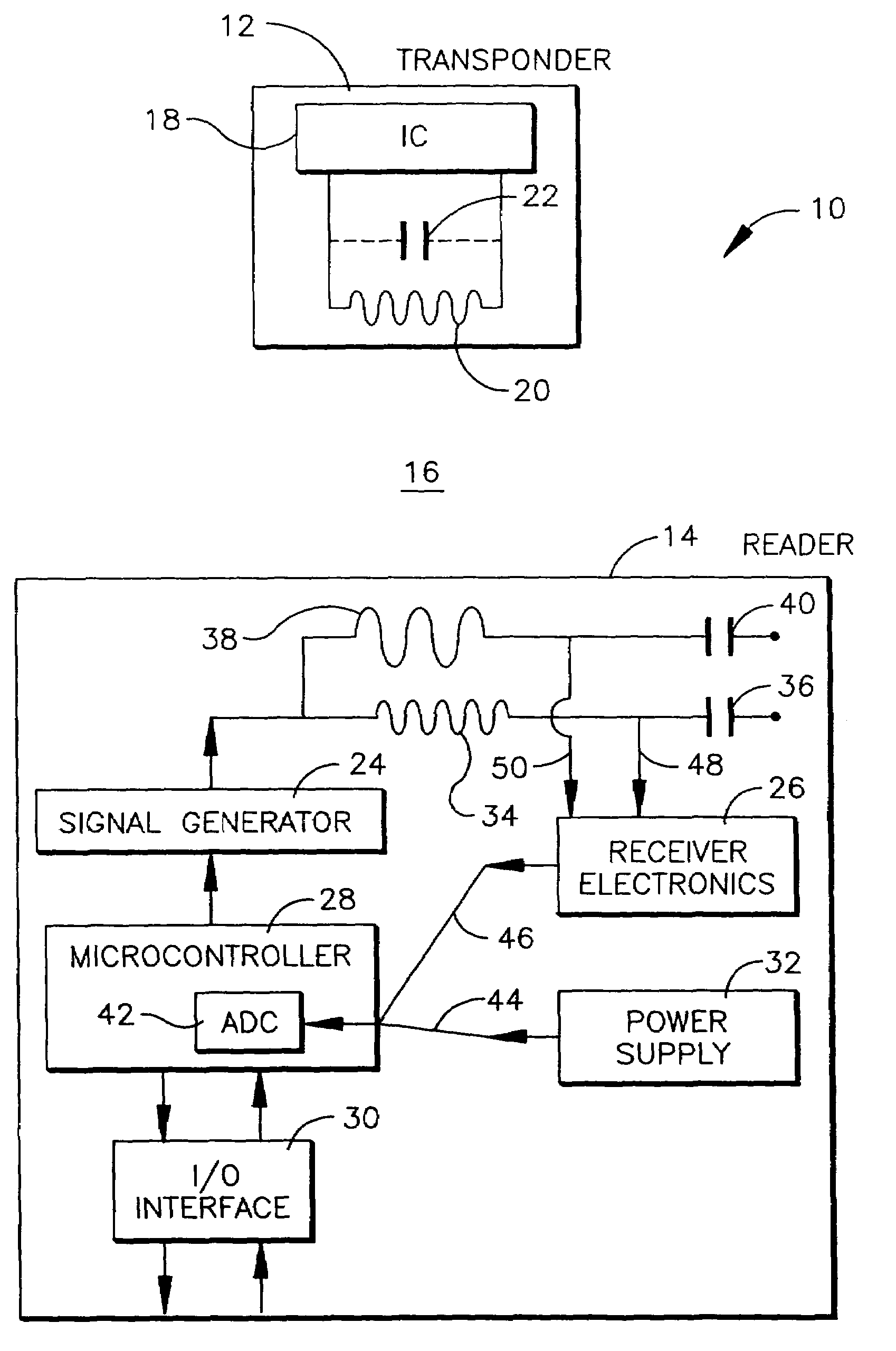
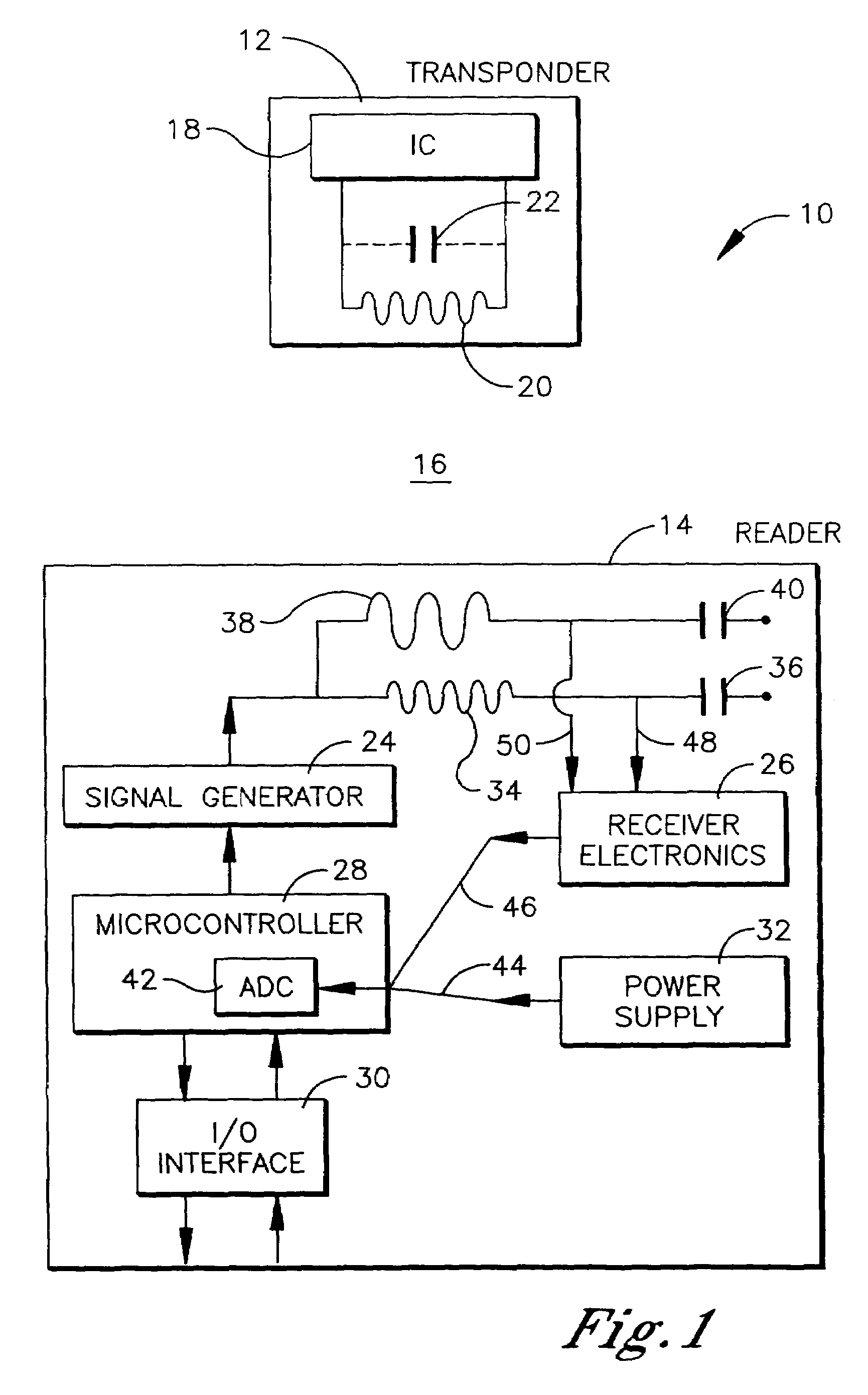
[0035]Referring initially to FIG. 1, a conceptualized embodiment of an RFID system is shown and generally designated 10. The RFID system 10 comprises a transponder 12 and a reader 14. The reader 14 is a preferred embodiment of a reader of the present invention and is described in greater detail hereafter.

[0036]The embodiment of the transponder shown herein is a passive device. As such, the transponder 12 is not physically coupled with an electrical power supply. The electrical power required to operate the transponder 12 is indirectly supplied to the transponder 12 by electromagnetic waves, which are periodically propagated through open space 16 to the transponder 12 from the reader 14. The transponder 12 is only operational when it is receiving electromagnetic waves from the reader 14 of a specific frequency and of sufficient strength to power up the transponder 12.

[0037]The transponder 12 includes a transponder integrated circuit (IC) 18 and a transponder antenna 20 coupled with t...


PUM


Abstract

A reader for an RFID system includes an internal power source, a signal generator for generating a detection signal containing analog data and an excitation signal, a transmitting antenna for transmitting the detection and excitation signals, and a receiving antenna for receiving a transponder data signal from a transponder containing digital data. Receiver electronics are coupled with the receiving antenna for conditioning the transponder data signal before reading the digital data. The reader further includes a single-chip microcontroller coupled with the internal power source and the receiver electronics. The single-chip microcontroller has an analog to digital converter to measure the declining power level of the internal power source and to acquire the analog data from the detection signal and the digital data from the transponder data signal. The single-chip microcontroller also includes a firmware and / or software-based demodulator for demodulating the transponder data signal to read the digital data.

Description

TECHNICAL FIELD[0001]The present invention relates generally to RFID systems, and more particularly to the construction and operation of a reader in an RFID system.BACKGROUND OF THE INVENTION[0002]Radio frequency identification (RFID) systems generally consist of at least one host reader and a plurality of transponders, which are commonly termed credentials. The transponder is an active or passive radio frequency communication device, which is directly attached to or embedded in an article to be identified or otherwise characterized by the reader, or which is alternatively embedded in a portable substrate, such as a card, keyfob, tag, or the like, carried by a person or an article to be identified or otherwise characterized by the reader.[0003]A passive transponder is dependent on the host reader as its power supply. The host reader “excites” or powers up the passive transponder by transmitting high voltage excitation signals into the space surrounding the reader, which are received...

Claims


Application Information

Patent Timeline
Patent Type & Authority Patents(United States)
IPC IPC(8): H04Q5/22G06F13/42G08B13/14G06K7/00G06K7/08
CPCG06K7/0008G06K7/10128G06K7/086
Inventor QUAN, RALPH W.
Owner ASSA ABLOY AB
Learn More