
Automobile brake caliper for reducing noise

a technology for brake calipers and brake calipers, which is applied in the direction of brake elements, slack adjusters, braking members, etc., can solve the problems of frequent rattle noise, rattle noise generated by components, so as to eliminate unwanted vibration of parts and associated rattle nois

Inactive Publication Date: 2007-02-20
HYUNDAI MOTOR CO LTD
View PDF16 Cites 4 Cited by
  • Summary
  • Abstract
  • Description
  • Claims
  • Application Information

AI Technical Summary

Benefits of technology

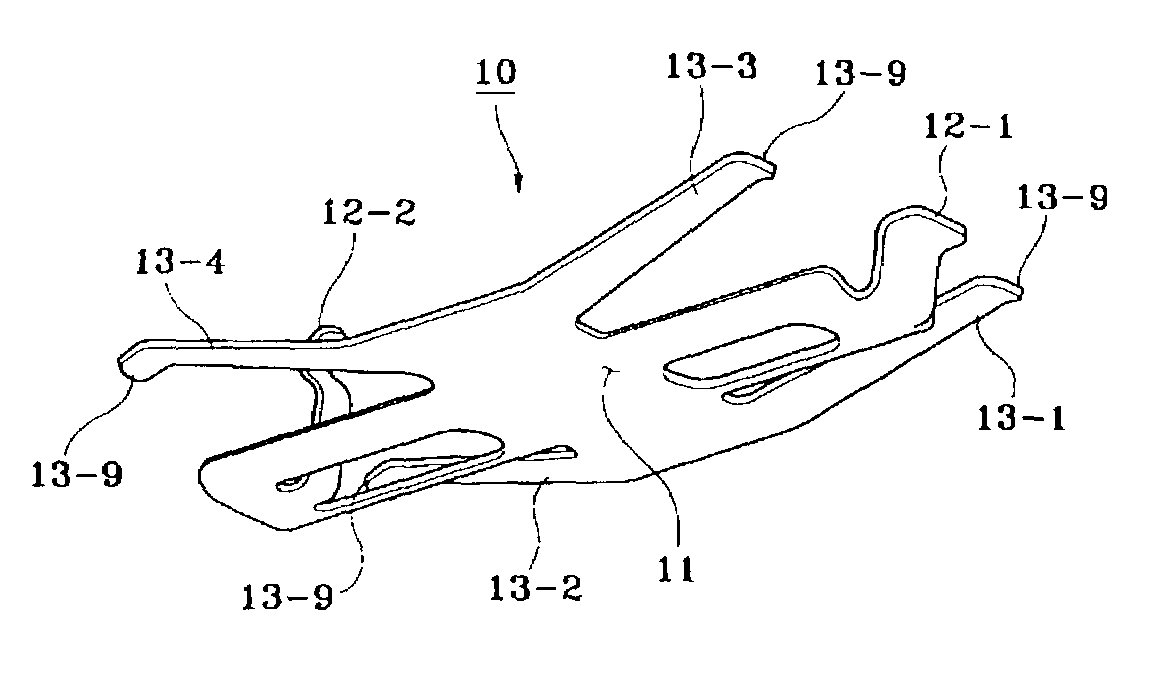
[0005]The present invention provides an automobile brake caliper in which elastic forces are applied between the components of the caliper to provide a dampening effect, whereby even if the automobile is subject to frequent vibrations when running over rough terrain, the components of the caliper avoid frictional contact, thereby reducing or preventing rattle noise.
[0007]In an alternative embodiment, an automobile brake caliper comprises a caliper housing with a first part defining a cylinder and a bridge part extending from the first part and supporting a finger part facing the cylinder. A piston is received within the cylinder. A first shoe is mounted on the cylinder and a second shoe mounted on the finger part such that a disc of a disc brake may extend therebetween. An elastic member is disposed between at least one of the shoes and the bridge part. The elastic member exerts an elastic force against the shoe to eliminate unwanted vibration of the parts and associated rattle noise. Preferably, the elastic member is disposed between the bridge part and both the first and second shoes, and exerts force against both shoes. In a preferred alternative embodiment, the bridge part defines an installing slot configured and dimensioned for installation of the elastic member between the bridge part and at least one shoe after assembly of the brake caliper.

Problems solved by technology

However, in conventional brake systems, rattle noise will frequently occur when an automobile runs over a rough terrain.
Rattle noise is generated from the impact of the movement of two or more metal components when they collide by external forces.
In the conventional caliper, rattle noise is generated when the components such as the caliper housing, the shoe and the mounting bracket collide due to the vibrations caused when the automobile runs over a rough terrain.
In this method, however, the improvement of the precision is accompanied by an increase in the manufacturing cost, and defective products are frequently generated.
Accordingly, this method has not been effective.
Further, when the caliper is used for a long time, the actuation parts of the components wear out, thereby regenerating the rattle noise.

Method used


Image

  • Automobile brake caliper for reducing noise
  • Automobile brake caliper for reducing noise
  • Automobile brake caliper for reducing noise

Examples


Embodiment Construction

[0013]Hereinafter, the preferred embodiment of the present invention will be described in detail by referring to the attached drawings. Here, the elements which are identical to the conventional elements will be assigned with identical reference numbers.

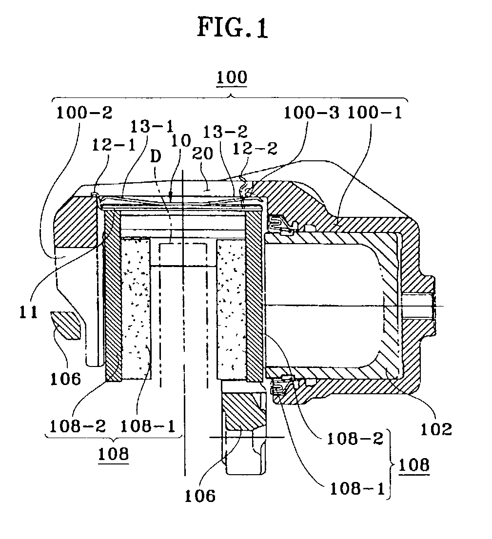
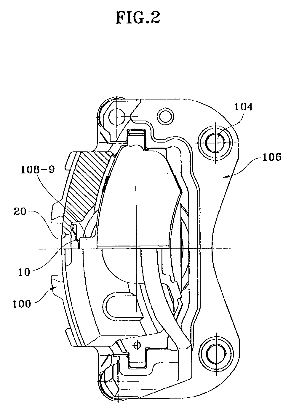
[0014]A preferred embodiment of the present invention is shown in FIGS. 1 and 2. Caliper housing 100 includes a cylinder 100-1 that allows piston 102 to move in response to hydraulic pressure. Finger part 100-2 faces toward the cylinder 100-1. Bridge part 100-3 joins the cylinder 100-1 and the finger part 100-2 such that the disc D may be disposed therebetween. A mounting bracket 106 is secured to a knuckle of the automobile wheel to slidably support the caliper housing 100 along guide pins 104. Piston 102 is received in cylinder 100-1 and moves in response to a supplied hydraulic pressure. Shoe 108 comprises a pad 108-1 and a back plate 108-2, the pad 108-1 preferably being attached to the back plate 108-2 with an adhesive.

[0015]An ...


PUM


Abstract

An automobile brake caliper for reducing noise is disclosed. An elastic member is installed so that elastic forces can act between the respective components. Thus, when the automobile generates vibrations while running over a rough terrain, the adjacent components avoid frictional contact, thereby eliminating any impact noise.

Description

FIELD OF THE INVENTION[0001]The present invention relates to an automobile brake caliper for reducing noise, and more particularly, to an automobile brake caliper including an elastic member dampening the moveable parts against vibration.BACKGROUND OF THE INVENTION[0002]When a disc brake is engaged, the pressing of the pedal by the driver is converted to hydraulic pressure through a booster and a master cylinder so as to transmit the hydraulic pressure to a caliper. Then the caliper presses a disc fixed with pads utilizing the hydraulic pressure, thereby generating a braking force.[0003]However, in conventional brake systems, rattle noise will frequently occur when an automobile runs over a rough terrain. Rattle noise is generated from the impact of the movement of two or more metal components when they collide by external forces. In the conventional caliper, rattle noise is generated when the components such as the caliper housing, the shoe and the mounting bracket collide due to t...

Claims


Application Information

Patent Timeline
IPC IPC(8): F16D65/40F16D65/097F16D65/00F16D65/02F16D65/092
CPCF16D65/0012F16D65/02
Inventor KANG, DONG-HOON
Owner HYUNDAI MOTOR CO LTD
Learn More