
A contact rail telescopic connector without expansion joints

A technology of contact rails and connectors, applied in the direction of power rails, power lines, vehicle components, etc., can solve problems such as unfavorable current reception, abnormal noise, damage, etc., to eliminate unstable current reception, eliminate impact abnormal noise, and realize electrical conduction The effect of connection

Active Publication Date: 2021-09-17
GUANGDONG POWER GRID CO LTD DONGGUAN POWER SUPPLY BUREAU +1
View PDF11 Cites 0 Cited by
  • Summary
  • Abstract
  • Description
  • Claims
  • Application Information

AI Technical Summary

Problems solved by technology

[0004] For this reason, the embodiment of the present invention provides a contact rail telescopic connector without expansion joints to solve the problem that in the prior art, the expansion joints are integral joints. The part of the flow device passing through the expansion joint is in a suspended state, and it is easy to have a slight impact with the docking contact rail after passing through the gap, making abnormal noise and may cause visible or potential damage

Method used


Image

  • A contact rail telescopic connector without expansion joints
  • A contact rail telescopic connector without expansion joints
  • A contact rail telescopic connector without expansion joints

Examples


Embodiment Construction

[0025] The implementation mode of the present invention is illustrated by specific specific examples below, and those who are familiar with this technology can easily understand other advantages and effects of the present invention from the contents disclosed in this description. Obviously, the described embodiments are a part of the present invention. , but not all examples. Based on the embodiments of the present invention, all other embodiments obtained by persons of ordinary skill in the art without making creative efforts belong to the protection scope of the present invention.

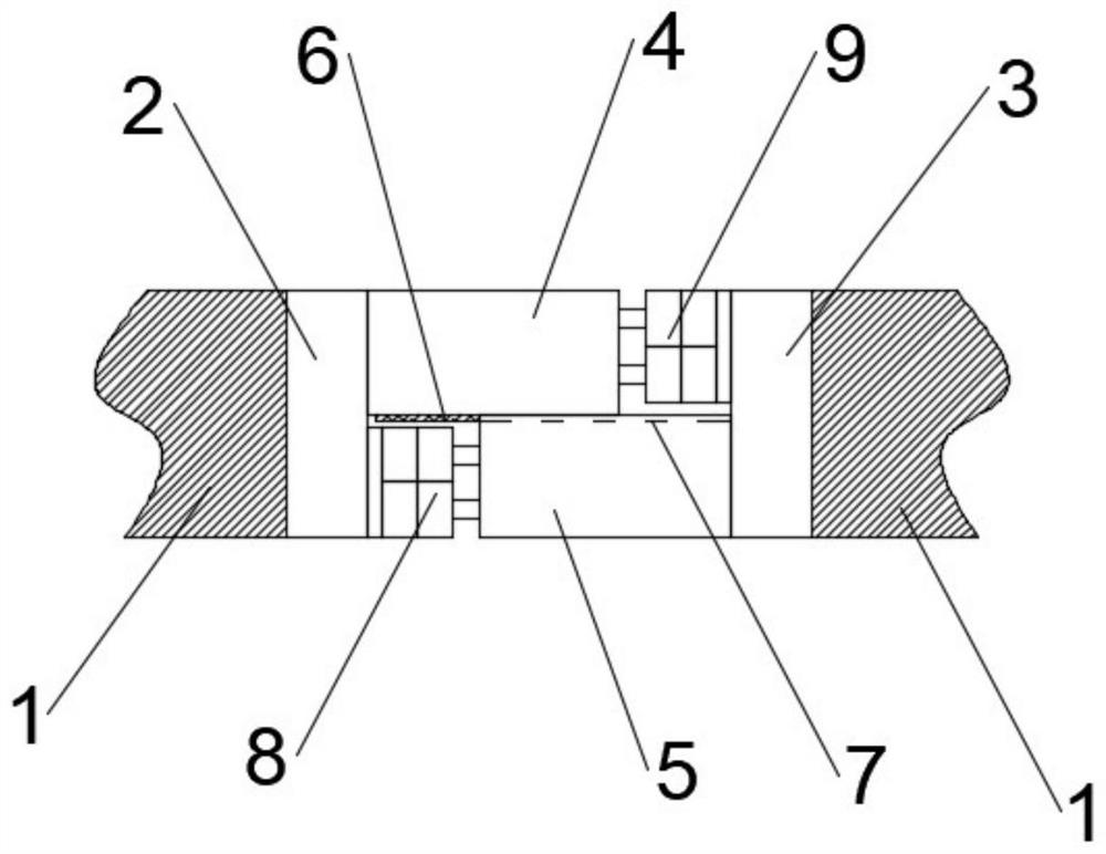
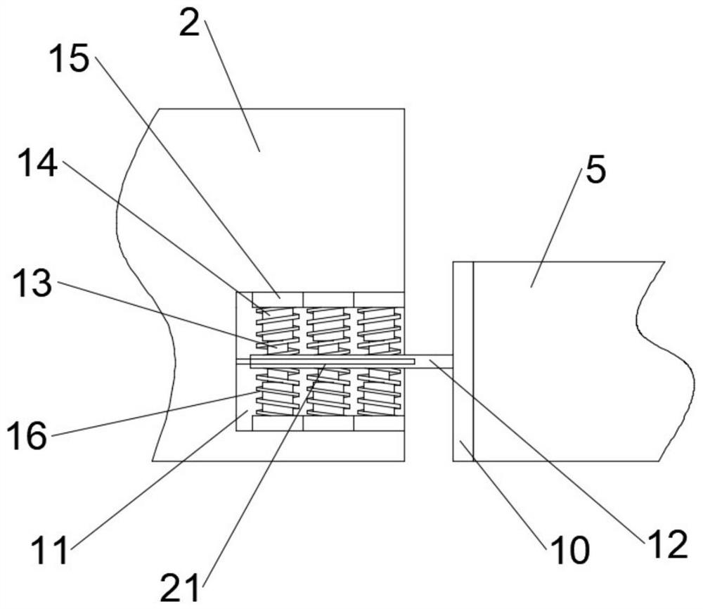
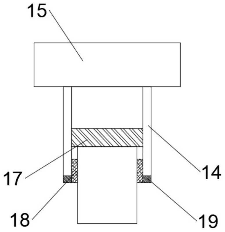
[0026] Such as Figure 1 to Figure 4 As shown, the embodiment of the present invention provides a contact rail telescopic connector without expansion joints, which is arranged between two adjacent sections of contact rail 1. The connector includes an A-end connecting seat 2 and a B-end connecting seat 3. A The end connection seat 2 and the B-end connection seat 3 are respectively arranged at the...


PUM


Abstract

The invention discloses a contact rail telescopic connector without expansion joints, which is arranged between two adjacent sections of contact rails. The connector includes an A-end connecting seat and a B-end connecting seat, and the A-end connecting seat and The B-end connecting seats are respectively arranged at the ends of two adjacent contact rails, the right end face of the A-end connecting seat faces the left end face of the B-end connecting seat, and the upper right end of the A-end connecting seat An upper connecting rail is provided, and a lower connecting rail is provided at the lower part of the left end of the B-end connecting seat, and the upper connecting rail and the lower connecting rail are interlaced up and down and the upper connecting rail is located above the lower connecting rail, The lower end surface of the upper connecting rail is provided with a power receiving slider, and the upper end surface of the lower connecting rail is provided with a power receiving chute. The power receiving chute slides inside, so that the two contact rails always maintain electrical conduction.

Description

technical field [0001] The invention relates to the field of contact rail connectors, in particular to a contact rail telescopic connector without expansion joints. Background technique [0002] When installing the contact rail, due to the influence of thermal expansion and contraction, it is necessary to reserve expansion joints between adjacent contact rails. When the temperature of the rail body rises, the two sections of the rail body will elongate in the direction of the reserved expansion joint, and the The gap becomes smaller, and vice versa. Through actual use, it is found that when the current collector passes through the expansion joint with expansion joints, the collector sliding shoes are affected by the expansion joints. The larger the joint, the greater the impact, and the faster the speed, the more obvious the impact. From the normal plane contact state The attitude changes, and after completely passing the expansion joint, it returns to the normal plane cont...

Claims


Application Information

Patent Timeline
Patent Type & Authority Patents(China)
IPC IPC(8): B60M1/30
CPCB60M1/305
Inventor 谭柱洪张汉光陈灼光钟少婷
Owner GUANGDONG POWER GRID CO LTD DONGGUAN POWER SUPPLY BUREAU
Learn More