Method of manufacturing a movable contact unit to be disposed close to a magnetic sensor

a technology of movable contact unit and magnetic sensor, which is applied in the direction of movable contact, snap-action arrangement, instruments, etc., can solve the problem of material magnetization

Inactive Publication Date: 2007-02-20
PANASONIC CORP
View PDF6 Cites 6 Cited by
  • Summary
  • Abstract
  • Description
  • Claims
  • Application Information

AI Technical Summary

Benefits of technology

[0017](C) applying demagnetization to the movable contact.In step A, elastic metal plate material is processed into a downwardly opening dome shape to form the movable contact. In step C, the demagnetization is performed so that the residual magnetic flux density of the movable contact is smaller than the operation magnetic flux density of a magnetic sensor that is disposed near it. In the movable contact unit manufactured in such a manner, the demagnetization is performed until the residual magnetic flux density of the movable contact is smaller than the operation magnetic flux density of the magnetic sensor that is disposed near it, so that click operation feeling is obtained without producing an adverse effect of magnetism on the electronic apparatus. In the manufacturing method of a switch panel of the present invention, the movable contact unit is overlaid on a wiring board having a pair of an outer fixed contact and a central fixed contact that correspond to the movable contact so that the lower end of the outer periphery of the movable contact is mounted on the outer fixed contact. The movable contact included in the switch panel manufactured in such a manner is demagnetized. When the switch panel is mounted to an apparatus, an effect to a magnetic sensor or the like disposed for the other function have to be little considered. Therefore, the switch panel and the magnetic sensor can be disposed close to each other, and downsizing and thinning of the apparatus can be achieved.

Problems solved by technology

However, such a material can be magnetized due to its handling or the like.

Method used


Image

  • Method of manufacturing a movable contact unit to be disposed close to a magnetic sensor
  • Method of manufacturing a movable contact unit to be disposed close to a magnetic sensor
  • Method of manufacturing a movable contact unit to be disposed close to a magnetic sensor

Examples


Embodiment Construction

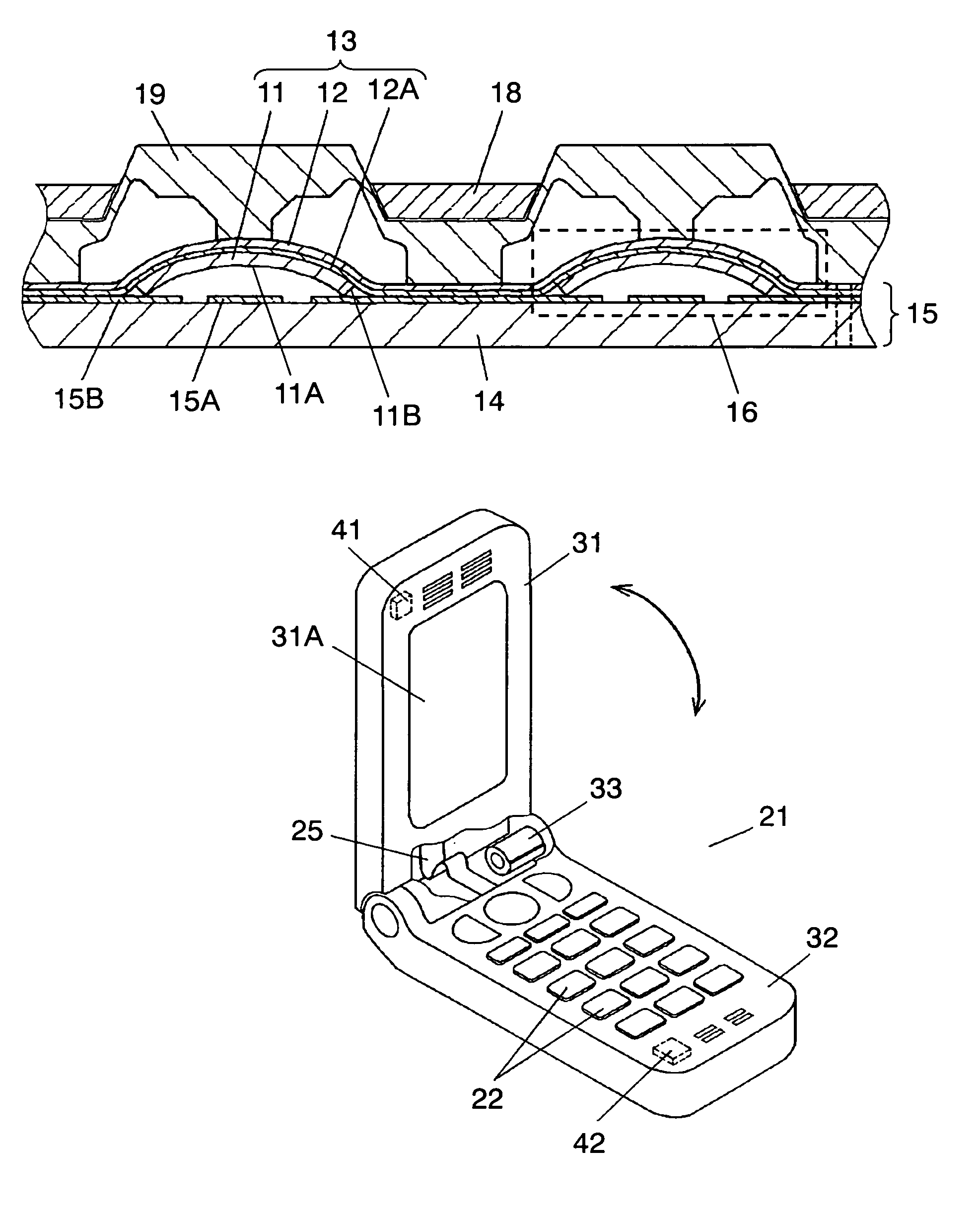
[0024]FIG. 1 is a sectional view of a movable contact unit in accordance with an exemplary embodiment of the present invention. FIG. 2 is a sectional view of an essential part of an electronic apparatus having a switch panel using the movable contact unit of FIG. 1.

[0025]Flexible and electrically insulating base sheet 12 is processed so that the outer shape is constant. Adhesive layer 12A is disposed on the whole lower surface. Each of movable contacts 11 is formed in downwardly opening dome shape. The upper surface of each movable contact 11 is stuck and held independently by adhesive layer 12A. Movable contact unit 13 is thus configured. Movable contact 11 is formed in the downwardly opening dome shape by drawing of a thin elastic metal sheet, and undergoes demagnetization. For the material of the thin elastic metal sheet, austenitic stainless steel is preferable from the viewpoint of the spring characteristic. SUS 301 containing 17 wt % of chrome and 7 wt % of nickel has a good s...


PUM


Abstract

A method of manufacturing a movable contact unit includes manufacturing a movable contact, sticking the movable contact to a base sheet made of insulating resin, and applying demagnetization to the movable contact so that the residual magnetic flux density is smaller than the operation magnetic flux density of the magnetic sensor. In manufacturing the movable contact, elastic metal plate material is processed into a downwardly opening dome shape to form the movable contact. In a method of manufacturing a switch panel, the movable contact unit is overlaid on a wiring board having a contact, including pair an outer fixed contact and a central fixed contact, that corresponds to the movable contact so that the lower end of the outer periphery of the movable contact is mounted on the outer fixed contact.

Description

CROSS REFERENCE TO RELATED DOCUMENTS[0001]This application claims priority to the Japanese Patent Application No. 2004-305474, filed on Oct. 20, 2004.BACKGROUND OF THE INVENTION[0002]1. Field of the Invention[0003]The present invention relates to a movable contact unit used in operation units of various electronic apparatuses, a method of manufacturing the movable contact unit, and a method of manufacturing a switch panel.[0004]2. Background Art[0005]Recently, various electronic apparatuses such as portable phones or personal digital assistants (PDAs) have been remarkably downsized and have had many functions. As an operation unit of each of the electronic apparatuses, a switch panel formed by disposing a plurality of pressing switches arranged in a predetermined array is used.[0006]A conventional movable contact unit used for forming such a switch panel and an electronic apparatus mounted with the switch panel using the movable contact unit are described with reference to FIG. 4 to...

Claims


Application Information

Patent Timeline
Patent Type & Authority Patents(United States)
IPC IPC(8): H01H11/00H01H65/00
CPCH01H13/7006H04M1/0245H04M1/23H01H13/88Y10T29/49155H01H2205/026H01H2229/00H01H2239/01H01H2239/024H01H2239/03H04M2250/12Y10T29/49789Y10T29/53891Y10T29/49105Y10T29/49117Y10T29/49147Y10T29/4913Y10T29/49204
Inventor MITSUOKA, HIDEKIKOYAMA, HIROMICHI
Owner PANASONIC CORP
Why Eureka
Try Eureka