
Optical head and optical recording medium drive device

Inactive Publication Date: 2007-02-13
SONY CORP
View PDF10 Cites 36 Cited by
  • Summary
  • Abstract
  • Description
  • Claims
  • Application Information

AI Technical Summary

Benefits of technology

[0013]An object of the present invention is to provide a novel optical head and a novel optical recording medium drive apparatus which can eliminate the problems that the prior arts have.
[0014]Another object of the present invention is to provide an optical head and an optical recording medium drive apparatus in which ratio between light power at the time of recording mode and light power at the time of reproduction is caused to be small to sufficiently reduce laser noise at the time of reproduction, and light source having small light output maximum rating is used so that satisfactory recording / reproducing characteristics can be obtained.
[0015]A further object of the present invention is to provide an optical head and an optical recording medium drive apparatus in which laser noise at the time of reproduction can be sufficiently reduced also with respect to plural types of optical recording media having different optimum recording and / or reproduction light power and / or plural types of optical recording media such as multi-layer optical recording medium, or optical recording medium in which one recording layer is divided into plural recording areas, etc, and satisfactory recording and / or reproducing characteristics can be obtained with respect to respective recording layers of various types of optical recording media, or multi-layer optical recording media and / or respective plural recording areas of one recording layer even by using light source having small light output maximum rating.

Problems solved by technology

Namely, in the semiconductor laser, generally speaking, in the case where output is small, it is difficult to obtain stable oscillation so that laser noise becomes large.
The light source having large light output maximum rating as described above has the problems that not only its realization is very difficult, but also power consumption in the light source becomes large, etc.
In addition, when attempt is made to use such light source in the state where light output is small as in the case of time period of reproduction, laser noise becomes large so that satisfactory reproduction characteristic cannot be obtained.

Method used


Image

  • Optical head and optical recording medium drive device
  • Optical head and optical recording medium drive device
  • Optical head and optical recording medium drive device

Examples


Embodiment Construction

[0049]An optical head and an optical recording medium drive apparatus according to the present invention will now be described in detail with reference to the attached drawings.

[0050]It is to be noted that since examples which will be described below are preferred practical examples of the present invention, technically preferred various limitations (restrictions) are attached, but the present invention is not limited to these forms as long as there does not exist description to the effect that the present invention is limited.

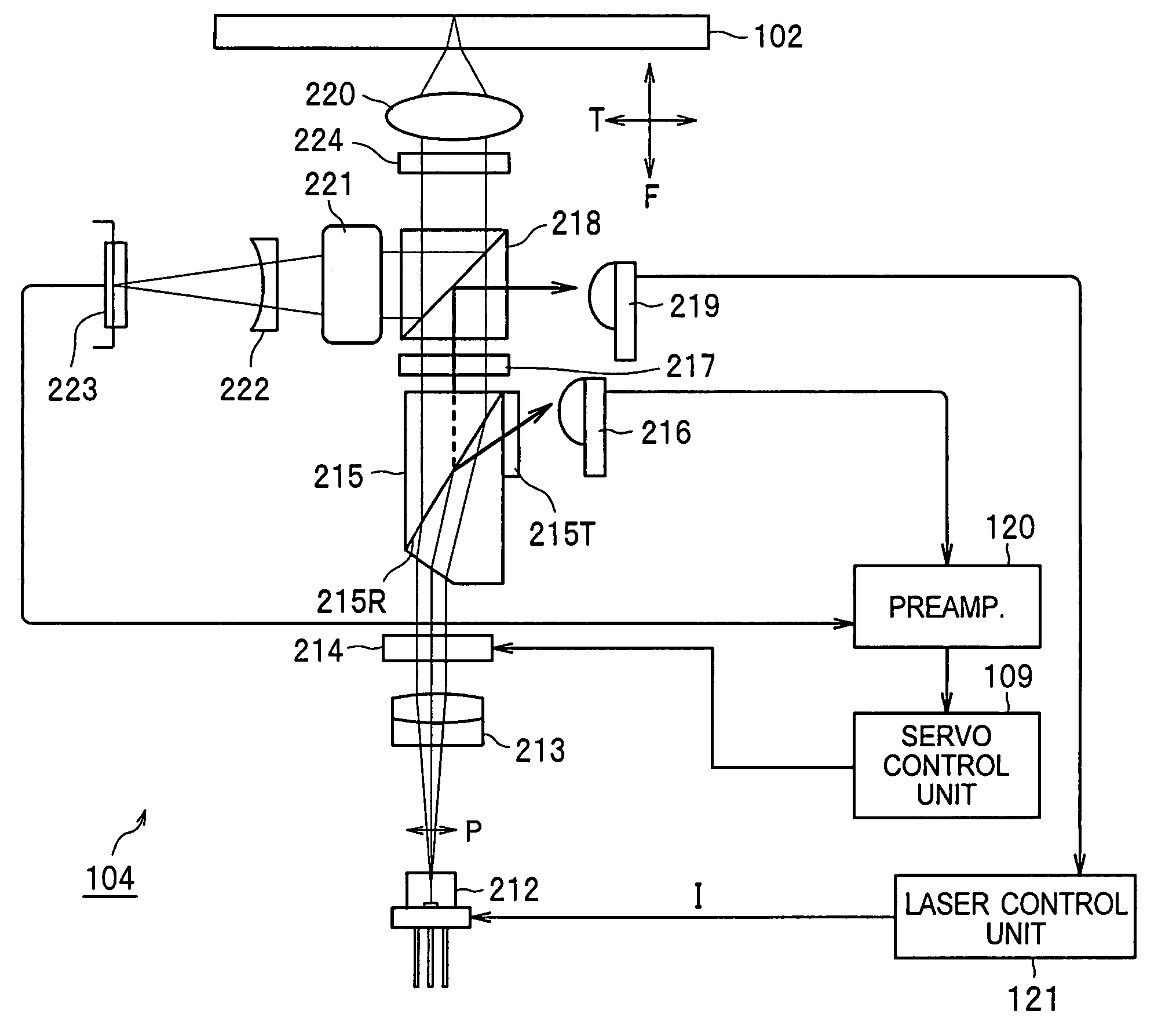
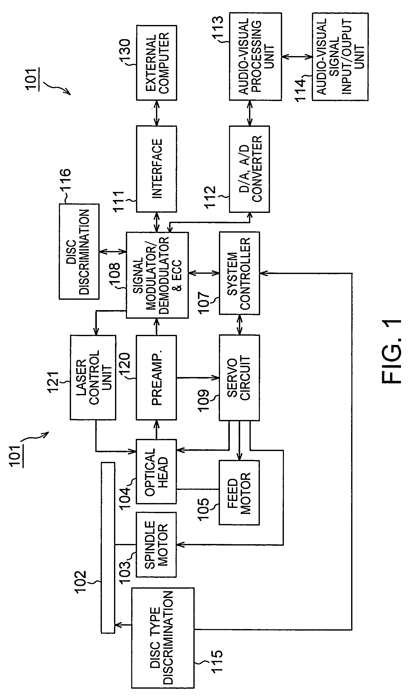
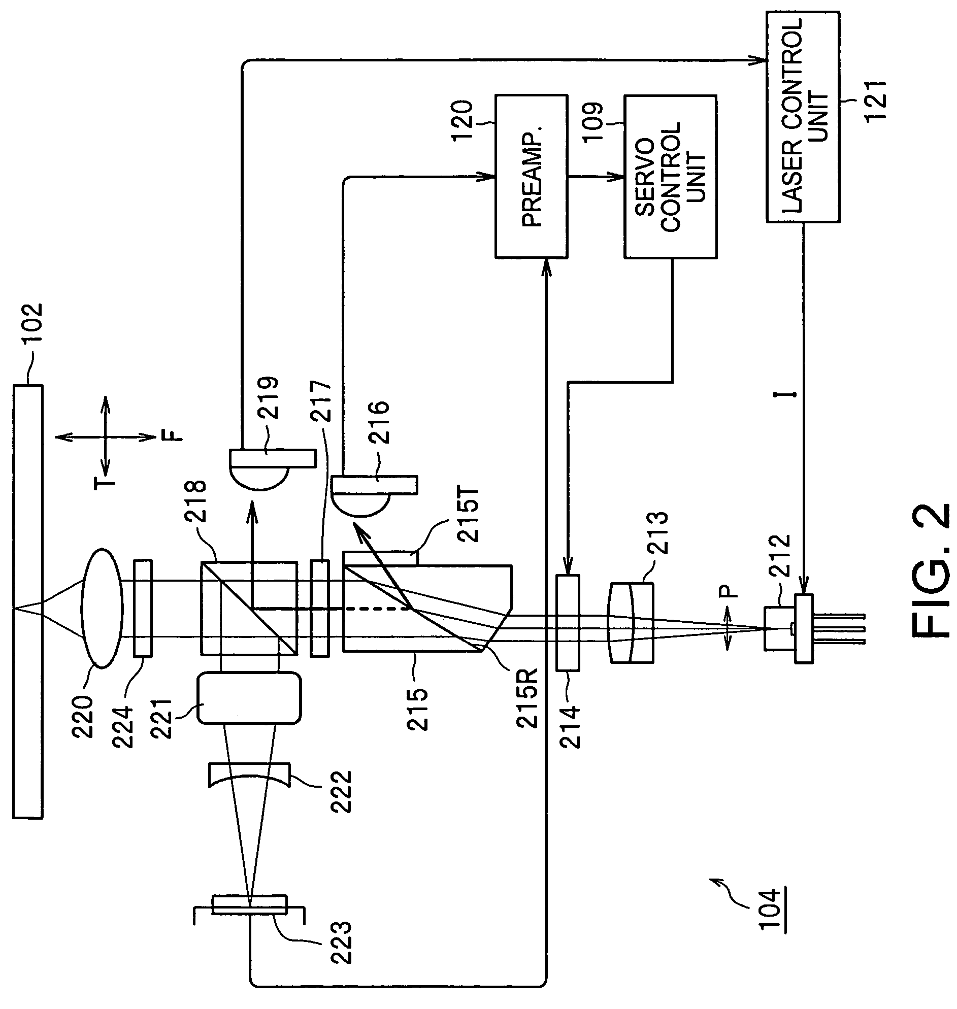
[0051]The optical recording medium drive apparatus 101 according to the present invention comprises, as shown in FIG. 1, a spindle motor 103 as drive means which rotationally operates an optical disc 102 which is optical recording medium, an optical head 104 according to the present invention, and a feed motor 105 for performing feed operation of the optical head 104 in the radial direction of the optical disc 102.

[0052]Here, the spindle motor 103 is driven by...


PUM


Abstract

The present invention is directed to an optical head adapted for performing recording or reproduction of information signals with respect to an optical disc (102), which controls light coupling efficiency with respect to light beams irradiated onto the optical disc (102) by light coupling efficiency adjustable element such as a liquid crystal element (214), etc. in accordance with type of the optical disc (102), recording surface of multi-layer optical disc and / or operation mode to change power of light beams irradiated onto the optical disc (102) to a large extent without excessively increasing change quantity of output power of a semiconductor laser element (212). A beam splitter (218) divides incident light beams of P-polarized light at a predetermined ratio to allow the light beams thus obtained to be incident on a light detector (219) for disc surface power monitor.

Description

TECHNICAL FIELD[0001]The present invention relates to an optical head and an optical recording medium drive apparatus which are adapted for recording various information with respect to optical recording media such as optical disc, etc., or performing reproduction of recorded information.[0002]This Application claims priority of Japanese Patent Application No. 2002-251795, filed on Aug. 29, 2002, the entirety of which is incorporated by reference herein.BACKGROUND ART[0003]Hitherto, optical discs are widely used as an optical recording medium. As the optical disc, there are used an optical disc of the reproduction only type in which information signals have been recorded in advance by micro uneven patterns, and / or an optical disc in which phase change material or magneto-optical material is used for recording layer to permit recording of information signals.[0004]Among them, in an optical recording medium drive apparatus such as optical disc apparatus, etc. using, as recording mediu...

Claims


Application Information

Patent Timeline
IPC IPC(8): G11B7/00G11B7/125G11B7/135
CPCG11B7/1263G11B7/128G11B7/1369G11B7/1356G11B2007/0013G11B2007/0006
Inventor NISHI, NORIAKITEZUKA, MASARUHASHIMOTO, KUNIKA
Owner SONY CORP
Learn More