Wear indicator for a roller

Inactive Publication Date: 2007-02-13
HAUNI MASCHINENBAU AG
View PDF10 Cites 12 Cited by
  • Summary
  • Abstract
  • Description
  • Claims
  • Application Information

AI Technical Summary

Benefits of technology

[0006]It is an object of the present invention to monitor and ensure quality during the production of filter rods and / or filter strands, wherein the process of quality assurance and monitoring should be easy and low cost.
[0010]According to one embodiment of the invention, the layers are different and / or distinguishable, wherein the differences and / or distinguishing features relate to the layer characteristics. For example, the layers can consist of different materials or have a different composition, which may not be optically discernable when viewing the roller. In contrast, distinguishable layers can also consist of the same material. By forming several different layers, for example, it is possible to produce a harder core covering and a softer use covering for the roller. Depending on the degree of use of the roller, a suitable wear-resistant covering can thus be produced. A somewhat harder covering mixture can be formed in particular in the regions of high wear.
[0011]The layers of one alternative embodiment of the invention can differ and / or become distinguishable as a result of wear on the covering. For example, it may not be possible to distinguish between the layers when the roller is originally installed. However, the covering and / or the layers are worn down during the operation, such that any wear becomes visible and is indicated. The wear on the covering caused by the filter strand production process can be detected easily as a result of the changes occurring in the roller layers.
[0012]It is preferable if the layers are optically different and / or can be optically distinguished. Being able to detect wear optically allows the operating personnel to recognize easily and quickly if a roller is worn out and must be replaced. Using different colors for the layers makes it easy to optically differentiate between the layers. For example, if a blue covering over the outer roller layer is worn down or worn off during the process of conveying the filter tow during the production, then the layer underneath, which may be red, is gradually exposed. Thus, the roller on the whole assumes a different color and indicates to the operating personnel an urgent need for replacing the roller. In addition, having several layers of different colors makes it possible to detect those regions on the roller, which are particularly subject to wear. If the covering surface becomes uneven, for example, the uneven roller can be refaced, so that it always has an even roller surface for the filter tow transport.
[0013]According to another embodiment of the invention, the layers are provided with at least one wear coating. A new wear coating can be applied to the roller once the original coating is worn off, thus resulting in a reduction of costs since only a replacement wear coating must be affixed to or arranged on the roller.
[0014]According to another aspect of the invention, there is provided a method of using a roller of the aforementioned type in a device for processing filter tow. By replacing the old rollers with rollers according to the invention, the production costs can be reduced since only the rollers must be replaced in the existing device.

Problems solved by technology

However, the roller covering wear clearly affects the filter quality after a specified production interval because the filter tow can no longer be transported and gathered to the required and desired degree.

Method used


Image

  • Wear indicator for a roller
  • Wear indicator for a roller
  • Wear indicator for a roller

Examples


Embodiment Construction

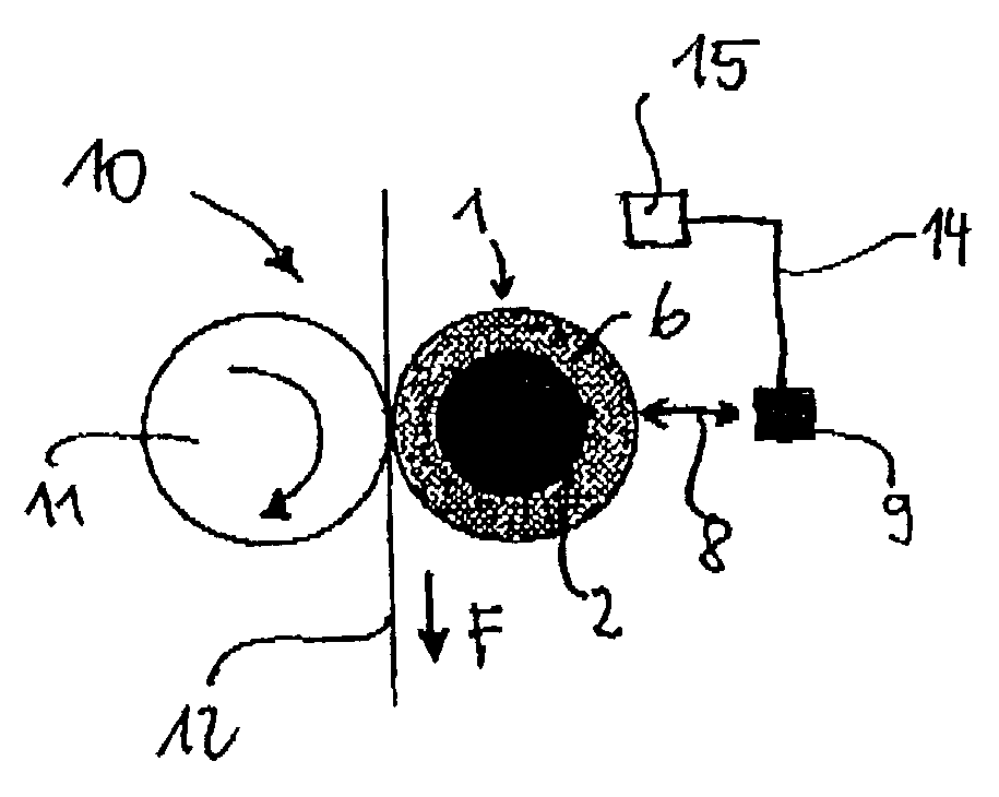
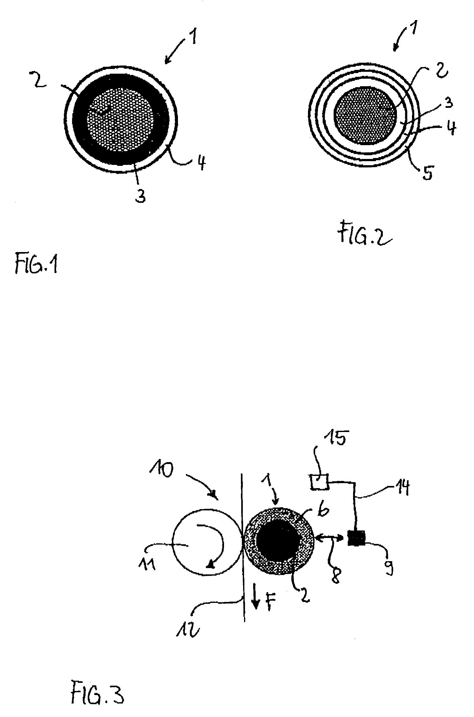
[0030]In the Figures, the same elements are given the same reference numerals and will not be introduced again.

[0031]FIG. 1 shows a cross-sectional view of a roller 1 with roller core 2, which roller belongs to a pair of rollers. A roller 1 of this type is used together with another roller having a grooved surface in a filter-tow-processing device for conveying a filter tow.

[0032]The roller core 2 can be composed of steel and has a cylindrical shape. The roller core 2 is enclosed by a first layer 3, which is enclosed by another layer 4. The layers 3 and 4 have different colors and furthermore consist of rubber. As a result of wear on the outer layer 4, the diameter of roller 1 gradually decreases during the production process. Thus, following a specific production interval, the different-colored surface of layer 3 becomes visible. The layer 4 represents a type of wear coating and ensures an even high quality during the production process. When layer 4 is worn off, a reliable conveyi...


PUM


Abstract

A roller for a device for processing a filter material ribbon in the tobacco-processing industry. The roller comprises a roller core and a covering for the roller core. The roller has at least one wear indicator operatively arranged for indicating wear of the covering.

Description

CROSS-REFERENCE TO RELATED APPLICATION[0001]This application claims the priority of German Patent Application No. 102 00 325.4 filed Jan. 7, 2002, the disclosure of which is incorporated herein by reference.BACKGROUND OF THE INVENTION[0002]The invention concerns a roller used in a device for processing a filter material ribbon in the tobacco-processing industry, the roller including a roller core and a covering for the roller core. The invention further concerns the use of such a roller. In addition, the invention concerns a device and a method for processing at least one filter material ribbon in the tobacco-processing industry with at least one roller having a roller core and at least one covering for the roller core.[0003]A device of this type is disclosed in European Patent document No. EP 654 224 B1. For the production of filter rods in the tobacco-processing industry, a filter-material ribbon, the so-called filter tow, of a composite fiber material such as cellulose acetate is...

Claims


Application Information

Patent Timeline
IPC IPC(8): B05C1/08A24D3/02
CPCA24D3/0295A24D3/02
Inventor WOLFF, STEPHANPETERS, STEPHANDITTOMBEE, HARALDPEHMOLLER, JURGENMEINS, THOMASFRICKE, VOLKERARNOLD, PETER-FRANZHORN, SONKEGLOGASA, JOACHIMMOJE, JENS
Owner HAUNI MASCHINENBAU AG
Why Eureka
Try Eureka