Portable electric router having radial fan

a technology of radial fan and electric router, which is applied in the direction of manufacturing tools, portable power-driven tools, wood mortising machines, etc., can solve the problems of increased noise, and achieve the effects of reducing noise, reducing noise, and improving cutting efficiency

Active Publication Date: 2007-02-06
KOKI HLDG CO LTD
View PDF11 Cites 16 Cited by
  • Summary
  • Abstract
  • Description
  • Claims
  • Application Information

AI Technical Summary

Benefits of technology

[0007]It is an object of the present invention to overcome the above-described problems and to provide a portable electric router capable of restraining noise, improving cutting efficiency and being manufactured at low cost with high assemble-ability with a reduced numbers of components.
[0009]With this arrangement, inertial moment of the cooling fan, and ultimately the inertial moment of the motor shaft assembly is increased to enhance cutting efficiency with an identical motor. Further, loudness of the noise is not increased even cooling through a narrow passage because of the employment of the radial fan. Moreover, because the guide section and the weight serve as a fan guide, the numbers of components can be reduced, to lower production cost.

Problems solved by technology

Further, loudness of the noise is not increased even cooling through a narrow passage because of the employment of the radial fan.

Method used


Image

  • Portable electric router having radial fan
  • Portable electric router having radial fan
  • Portable electric router having radial fan

Examples


first embodiment

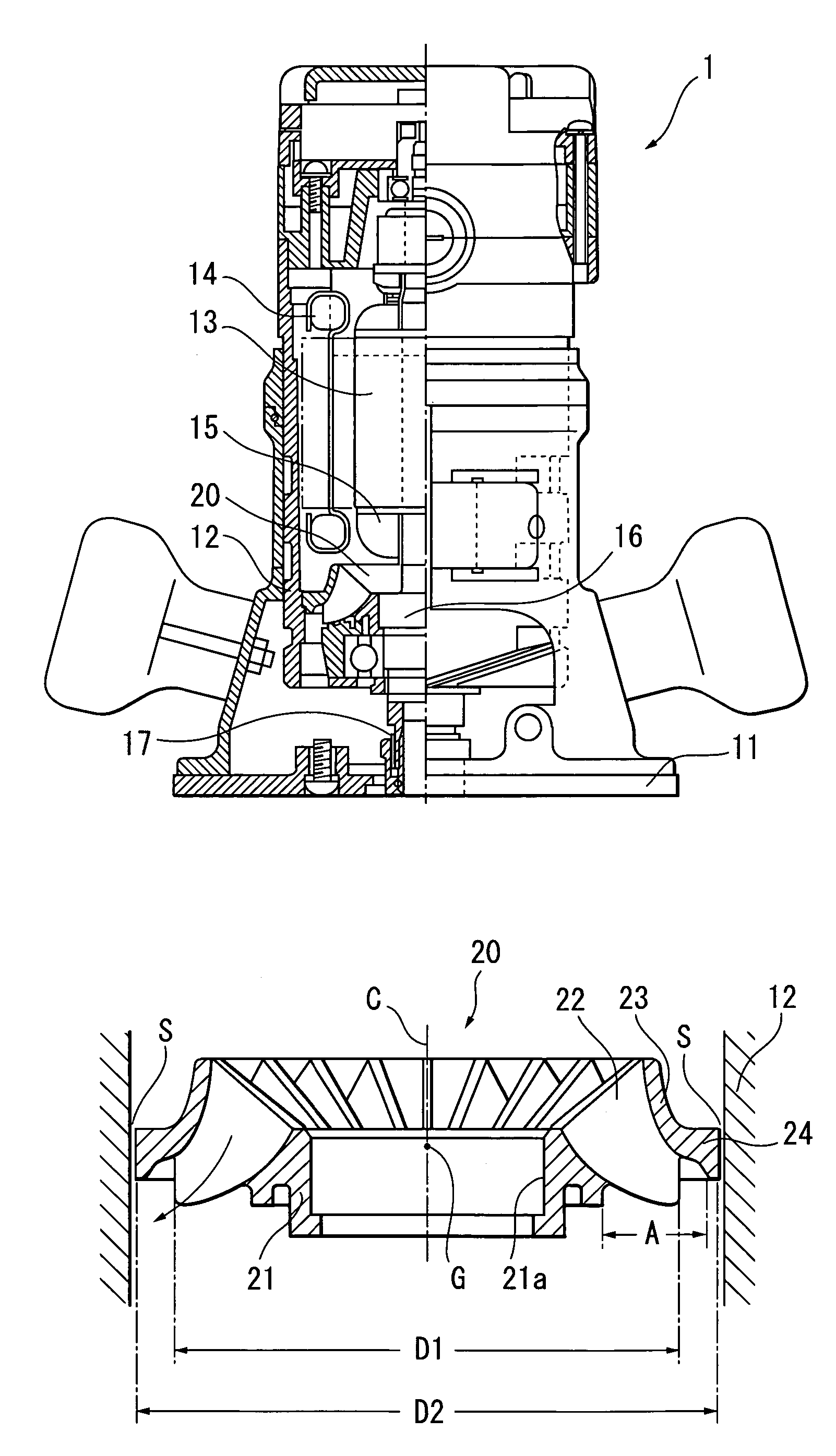
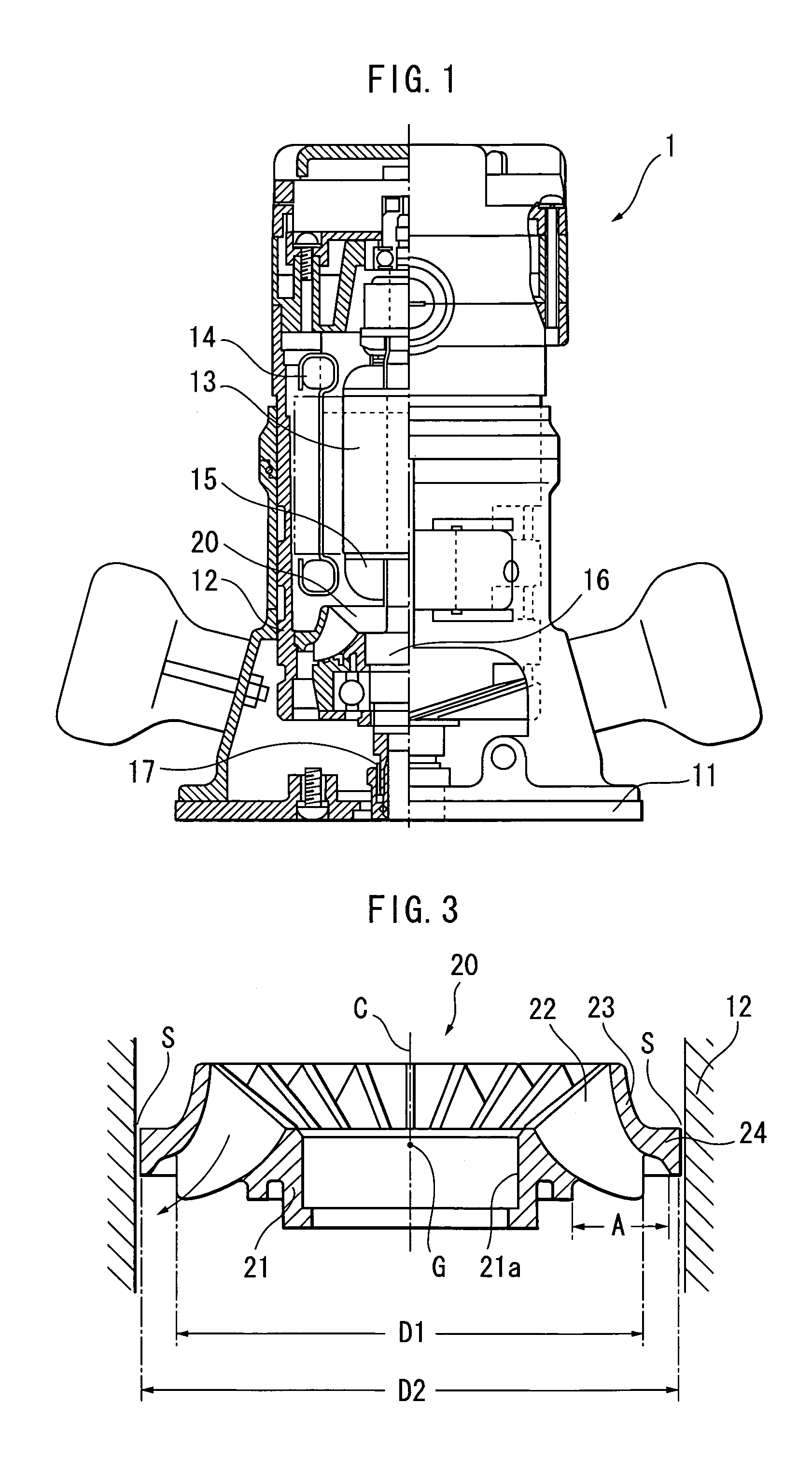
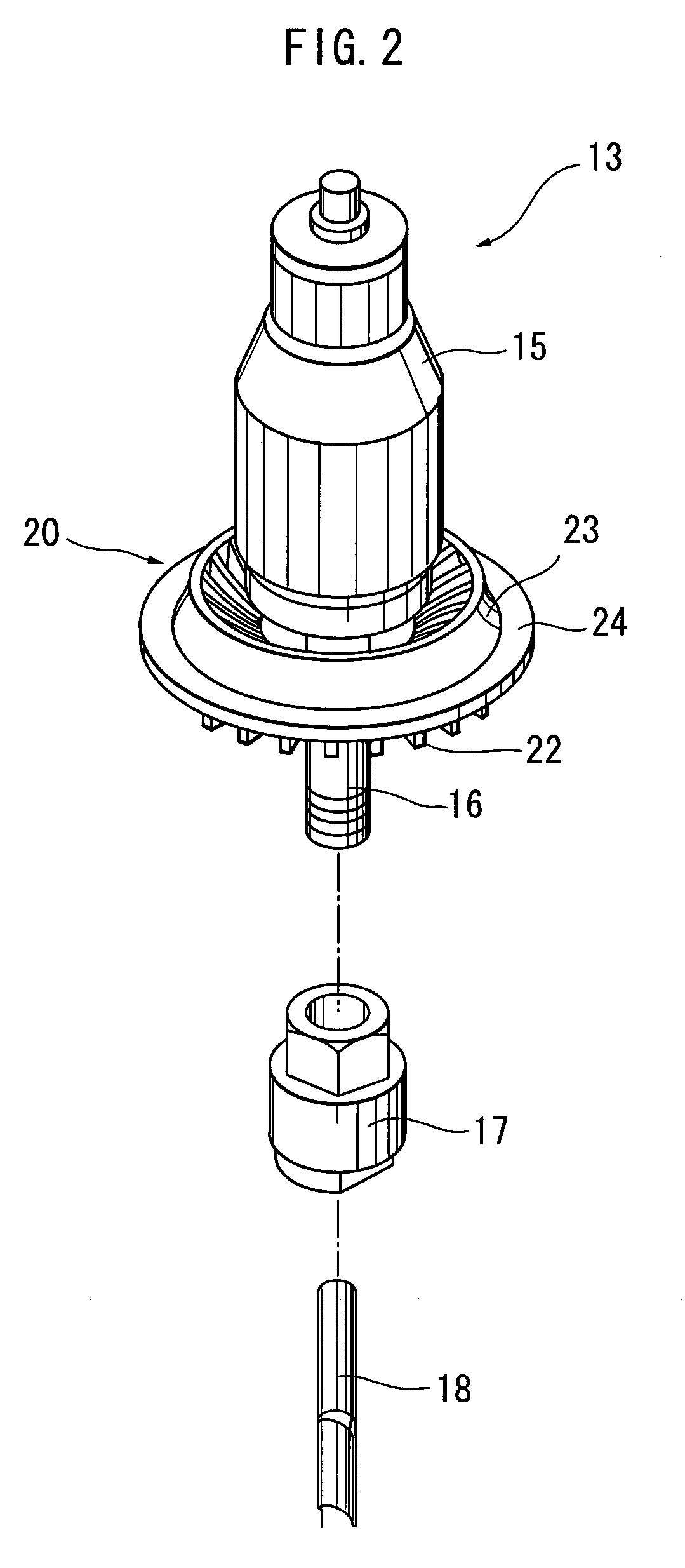
[0020]A portable electric router according to the present invention will be described with reference to FIGS. 1 through 3. As shown in FIG. 1, a portable electric router includes a base 11, a housing 12, an electric motor 13, and a chuck 17. The base 11 serves as a guide when sliding on a workpiece such as a wood. The housing 12 is in a cylindrical configuration and is movably supported through a support mechanism (not shown) on the base 11. The motor 13 is housed in the housing 12 and has a stator 14, an armature 15, and an armature shaft 16 serving as a motor shaft. The chuck 17 is attached to a lower end of the armature shaft 16 for holding a cutting bit 18 (FIG. 2).

[0021]FIG. 2 shows rotatable components of a motor 13 constituting the part of the portable electric router 1. The rotatable components include the armature 15 constructed from an armature coil, an armature core, a commutator, etc., the armature shaft 16, a cooling radial fan 20, and the chuck 17. The cooling radial f...

third embodiment

[0034]FIG. 5 shows a radial fan 220 constituting a portable electric router according to the present invention. According to this embodiment, each fan blade 222 is bent toward a direction opposite to the rotating direction Q with respect to a radial direction R from the central axis C. With this arrangement, a velocity of air flow passing between the neighboring fan blades 222, 222 becomes lower than the rotating velocity of the fan blade 222, to further reduce noise.


PUM

PropertyMeasurementUnit
outer diameter D2aaaaaaaaaa
distanceaaaaaaaaaa

Abstract

A compact and light-weight portable electric router produced at a low cost and capable of providing high cutting efficiency with low noise. A radial fan includes a cylindrical hub functioning as an attachment portion to a motor shaft, a plurality of fan blades having parts connecting to the hub, and a ring like guide section connected to the hub through the fan blades. An annular weight is connected to the guide section at a radially outer side of the guide section. The weight serves as a restriction section for restricting backflow of air from a discharge side to a motor side.

Description

BACKGROUND OF THE INVENTION[0001]The present invention relates to a portable electric power tool such as an electric router, and more particularly, to the portable electric router capable of performing chamfering and groove forming operations by rotating a rotary cutting bit fixed to a motor shaft.[0002]The portable electric router is a tool for performing chamfering or grooving work on a workpiece made of, for example, wood. This is an especially indispensable tool for producing furniture. FIG. 7 shows an example of a conventional portable electric router. The electric router includes a base 311, a housing 312, an electric motor (not shown), and a chuck 317. The base 311 serves as a guide when sliding on a work-piece W such as a wood. The housing 312 is movably supported on the base 311. The motor is housed in the housing 312 and has a motor shaft, whose lower end is provided with the chuck 317 for mounting a cutting bit 318 which may take on various forms. The bit 318 is rotated b...

Claims


Application Information

Patent Timeline
Patent Type & Authority Patents(United States)
IPC IPC(8): B27C5/10B23Q11/12B25F5/00H02K7/02H02K7/14H02K9/06
CPCB23Q11/127B27C5/10H02K7/02H02K9/06Y10T409/304088Y02E60/16Y10T409/306608H02K7/145B23Q11/12B25F5/008B27F5/02
Inventor NISHIKAWA, TOMOMASAONOSE, AKIRAOHTSU, SHINKI
Owner KOKI HLDG CO LTD
Why Eureka
Try Eureka