
Method for controlling a safety-critical system which has a microcontroller

a technology of safety-critical systems and microcontrollers, which is applied in the direction of program control, underwater vessels, non-deflectible wheel steering, etc., can solve the problems of disruption of the operating sequence microcontroller malfunctions, etc., and achieve the prevention of malfunctions of the motor vehicle, the effect of reducing power loss and reducing chip temperatur

Inactive Publication Date: 2007-01-30
SIEMENS AG
View PDF18 Cites 2 Cited by
  • Summary
  • Abstract
  • Description
  • Claims
  • Application Information

AI Technical Summary

Benefits of technology

[0009]One advantage of the invention is that by measuring the chip temperature of the chip which is composed of the semiconductor material it is possible to draw conclusions about the molecular movement of the semiconductor material. In this way it is easy to determine when the microcontroller is moving in the region in which its operating sequences are disrupted.
[0010]Thus, in one embodiment of the invention, it is possible to interrupt the operating sequence and / or program sequence when the maximum chip temperature is exceeded. In another embodiment, the measured chip temperature is supplied to an external evaluation device which caries out the temperature comparison and blocks the operating sequence and / or program sequence of the microcontroller by supplying an external signal. In this context, the external evaluation device can use software to decide whether the microcontroller is to continue to operate.
[0011]Another embodiment makes it possible for the measured chip temperature on the chip itself to be converted into a voltage change, the temperature comparison being carried out by a comparator circuit which is arranged in the microcontroller itself. By carrying out this blocking using hardware, which is a comparator circuit in the simplest case, the mode of operation of the microcontroller is immediately interrupted.
[0012]The chip temperature is advantageously set below the maximum chip temperature by regulating the operating sequences of the safety-critical system. This approach can be used favorably, for example, in systems which are themselves responsible for the increasing ambient temperatures of the microcontroller.
[0013]In another embodiment, when the permitted chip temperature is exceeded, the microcontroller which is arranged in the direct vicinity of a device which produces a power loss actuates the device which produces the power loss, in such a way that the power loss is reduced and as a consequence the chip temperature is decreased. This procedure ensures that, in a microcontroller which continuously operates at the maximum junction temperature, the safety-critical system can remain operational and malfunctions of the motor vehicle are prevented.
[0014]In still another embodiment, the reprogramming of a flash memory which is arranged on the chip and forms the peripheral microprocessor device is monitored as a function of the chip temperature. As the maximum flash temperature is monitored on the basis of this temperature monitoring, reliable data retention is ensured when flashing occurs. If the controller is to be flashed again using a diagnostic tool when it is in service, the temperature of the controller chip can be interrogated by means of software, and when the maximum flash temperature is exceeded flashing can be prevented. Flashing of the controller at interfaces, for example the JTAG interface, can be prevented by means of hardware on the chip.

Problems solved by technology

As the mode of operation of the microcontroller depends decisively on the molecular movement of the semiconductor material which bears the electronic parts, temperature changes in the environment of the microcontroller lead to malfunctions of the microcontroller and thus to disruption in the operating sequences of the motor vehicle.

Method used


Image

  • Method for controlling a safety-critical system which has a microcontroller
  • Method for controlling a safety-critical system which has a microcontroller
  • Method for controlling a safety-critical system which has a microcontroller

Examples


Embodiment Construction

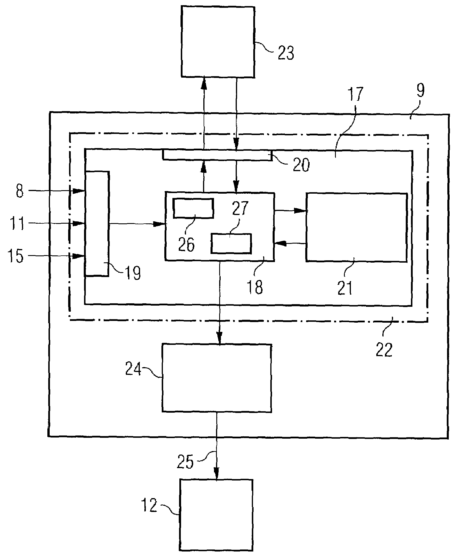
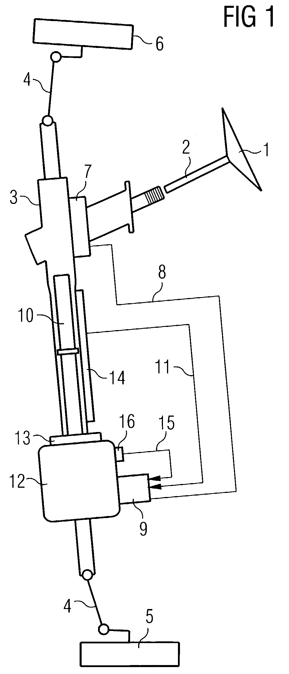
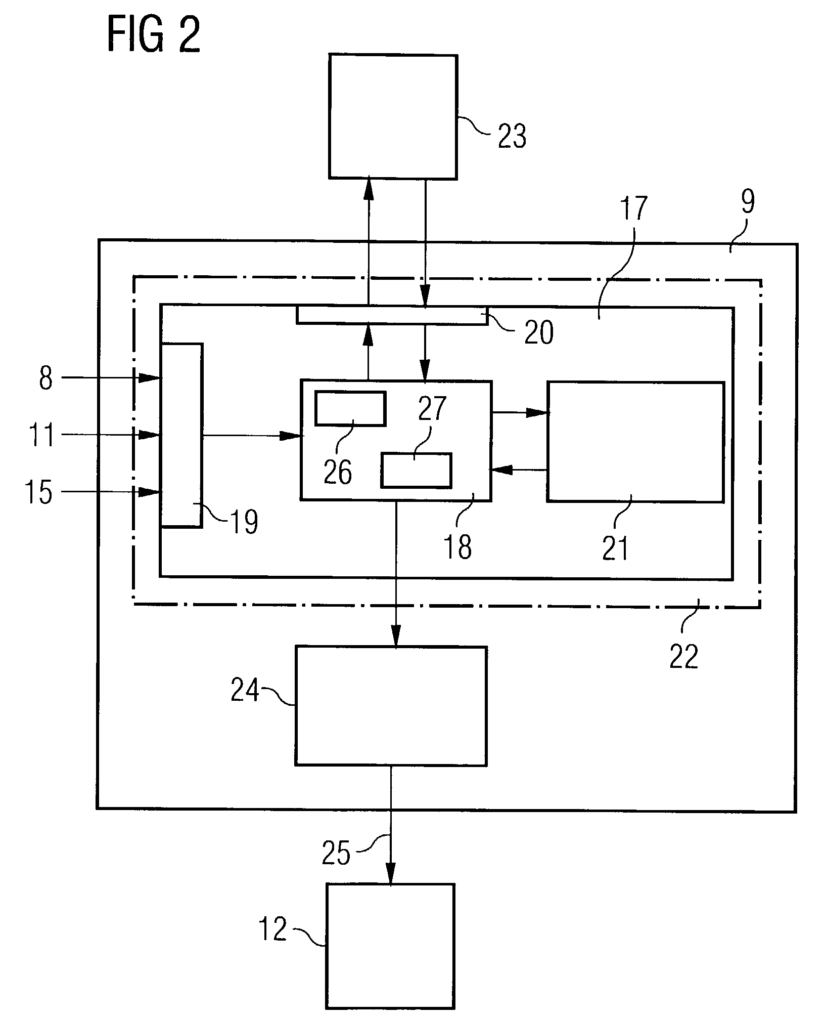
[0020]The invention will be explained by reference to the example of an electric power steering system. A steering column 2 which supports the steering wheel 1 engages in a steering gear 3 which moves the two front wheels 5 and 6 of a motor vehicle (not illustrated in more detail) via a steering linkage 4. A steering torque sensor 7, which is connected to a control unit 9 via the line 8, is arranged on the steering column 2. A linear travel sensor 10, which outputs sensor signals, which correspond to the rotational angle of the steering column 2, to the control unit 9 via the line 11 is arranged on the steering gear 3. An electric motor 12 is connected to the toothed rack 14 of the steering gear 3 via a recirculating ball mechanism 13. Furthermore, the position of the electric motor 12 which is detected by a motor position sensor 16 is signaled to the control unit 9 via a further line 15.

[0021]The control unit 9 whose basic structure is illustrated in FIG. 2 has, as a core unit, a m...


PUM

PropertyMeasurementUnit
temperatureaaaaaaaaaa
chip temperatureaaaaaaaaaa
ambient temperaturesaaaaaaaaaa

Abstract

The invention relates to a method for controlling a safety-critical system, in particular of a motor vehicle, which includes a microcontroller. The microcontroller controls and / or regulates the operating sequences of the safety-critical system, and the microcontroller is composed of a microprocessor and at least one peripheral microprocessor device. In a method for controlling a safety-critical system in which disruption to the operational reliability is to be prevented by changes in the molecular movement of the carrier of the microprocessor, the chip temperature of a chip which is provided with the microprocessor and peripheral device together is measured during an operating sequence and / or program sequence and compared with a maximum permitted chip temperature of the microcontroller. The operating sequence and / or the program sequence is controlled as a function of the temperature comparison.

Description

CLAIM FOR PRIORITY[0001]This application claims priority to Application No. 10163153.7 which was filed in the German language on Dec. 20, 2001.TECHNICAL FIELD OF THE INVENTION[0002]The invention relates to a method for controlling a safety-critical system, and in particular, to a motor vehicle, which has a microcontroller.BACKGROUND OF THE INVENTION[0003]Operating sequences of a motor vehicle are controlled or regulated by control units whose core is a microcontroller. The microcontroller contains control data which the control program requires in order to ensure the operating sequence of specific devices of the vehicle. Moreover, during the service life of a control unit the operating parameters of the device which is to be controlled by this control unit may also change and therefore need to be continuously determined again and stored in the microcontroller. Moreover, it is also necessary to adapt the control programs to changes in the operating parameters of the device to be cont...

Claims


Application Information

Patent Timeline
Patent Type & Authority Patents(United States)
IPC IPC(8): G06F11/00G01K7/00G05D23/00G08B29/00H02H5/04B62D5/04G05B9/02G05B19/048G06F1/20
CPCG06F1/206
Inventor HENNINGER, MICHAEL
Owner SIEMENS AG
Learn More