
Room acoustics echo meter for voice terminals

Active Publication Date: 2007-01-30
AVAYA INC
View PDF9 Cites 4 Cited by
  • Summary
  • Abstract
  • Description
  • Claims
  • Application Information

AI Technical Summary

Benefits of technology

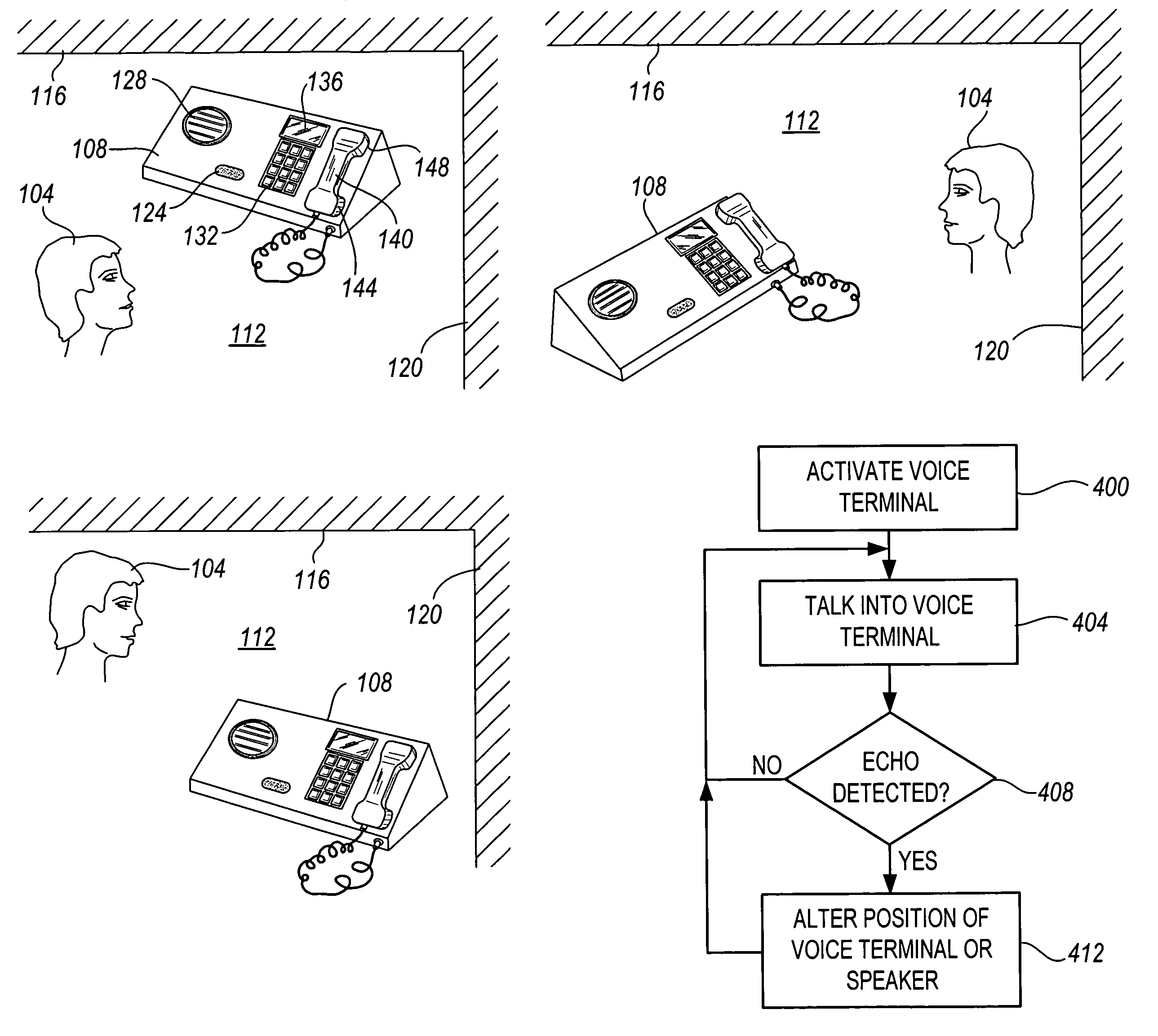
[0007]The present invention is directed to solving these and other problems and disadvantages of the prior art. Generally, according to the present invention, the presence of acoustic reverberation or echo in a voice signal is detected. The user or talker is then notified of the acoustic reverberation, so that the user can take appropriate steps to mitigate the acoustic reverberation. For example, in response to receiving an indication that acoustic reverberation is present, the user may ch

Problems solved by technology

Voice communication systems, including telephone systems, are subject to several sources of echo that make transmitted voices sound bad to listeners.
These echoes can noticeably degrade the intelligibility and quality of the transmitted voice signal.
However, it is often the case that people speaking into a speakerphone within small enclosed environments, such as offices or conference rooms, are unaware of such echoes.
However, such modifications can be expensive.
In addition, such modifications may not be possible or appropriate to all rooms in which the use of a speaker phone is desirable.
Furthermore, a change in the arrangement of furniture in a room, or in the position of the speaker phone within the room, can result in the introduction of echo to a transmitted voice signal, even though previously there had been no echo.
However, it is not always convenient or desirable to hold a handset or to wear a headset.
Furthermore, although microphones can be placed in front of individual talkers, for example in a conference call scenario with multiple talkers at a location using a speaker phone, the problem of acoustic reverberation at the physical location may not be entirely avoided.
However, directional microphones are relatively expensive, can be difficult to properly set up, and do not work well when a talker is moving about their physical location.
Although such techniques can be effective at reducing the effects of acoustic reverberation, they are relatively expensive to develop and deploy.

Method used


Image

  • Room acoustics echo meter for voice terminals
  • Room acoustics echo meter for voice terminals
  • Room acoustics echo meter for voice terminals

Examples


Embodiment Construction

[0019]The present invention is directed to signaling the presence of echo in a transmitted voice signal to a user.

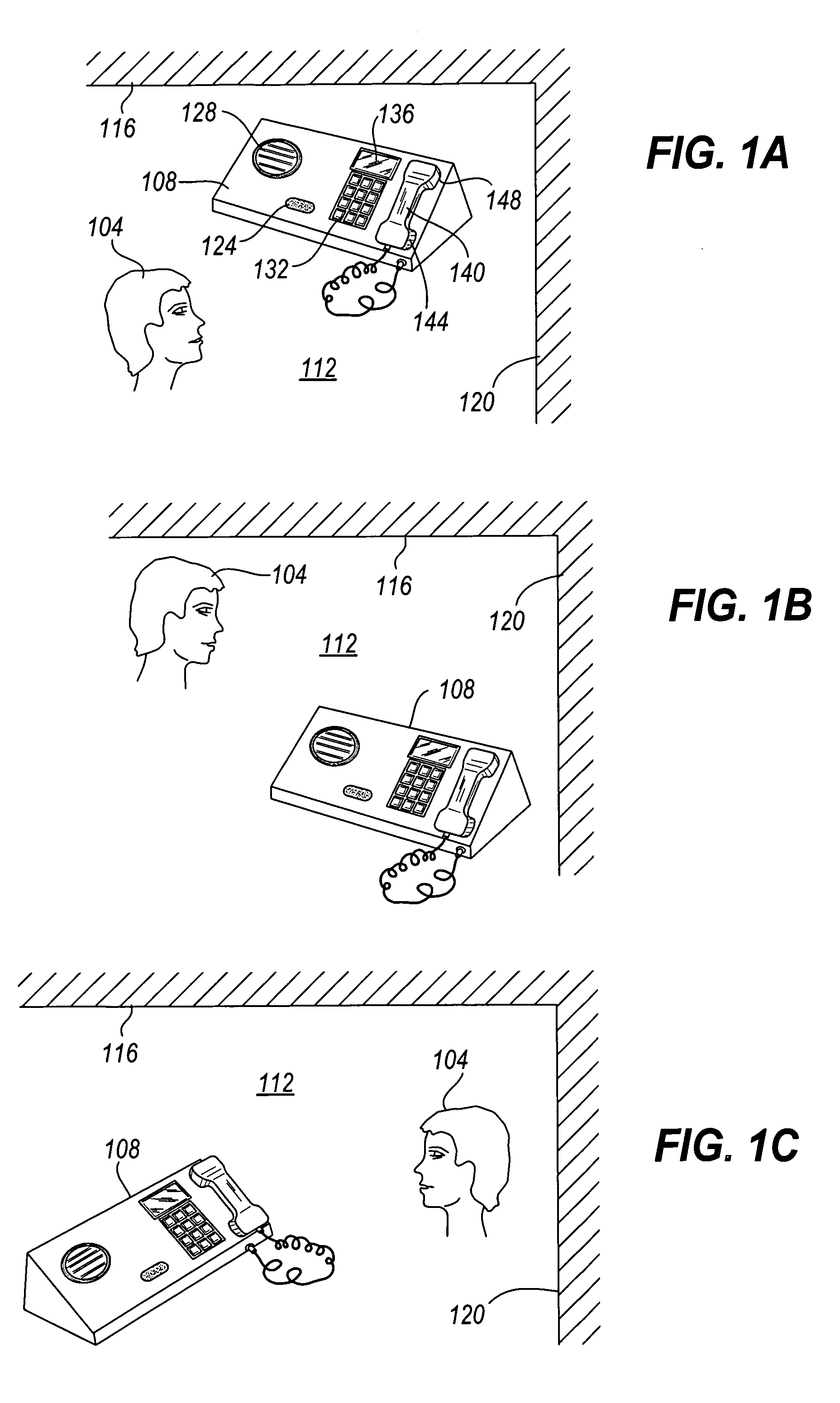
[0020]In FIGS. 1A to 1C, examples of different relative positions of a user or talker 104 and a voice terminal or voice communication device 108 within a room 112 are shown. In addition, a first wall 116 and a second wall 120 of the room 112 are illustrated. The voice terminal 108 generally includes a far talk microphone 124 and a broadcast speaker 128 for facilitating speaker phone operation. In addition, the voice terminal 108 illustrated in FIGS. 1A to 1C includes a key pad 132, a display 136, and a handset 140. The handset 140 in turn includes a microphone 144 and a speaker 148. As can be appreciated, not all of the features 124–148 illustrated in connection with the voice terminal 108 as shown in FIGS. 1A–1C must be provided. Furthermore, additional features may be provided if desired.

[0021]The voice terminal 108 may generally comprise a conventional telephone or sp...


PUM


Abstract

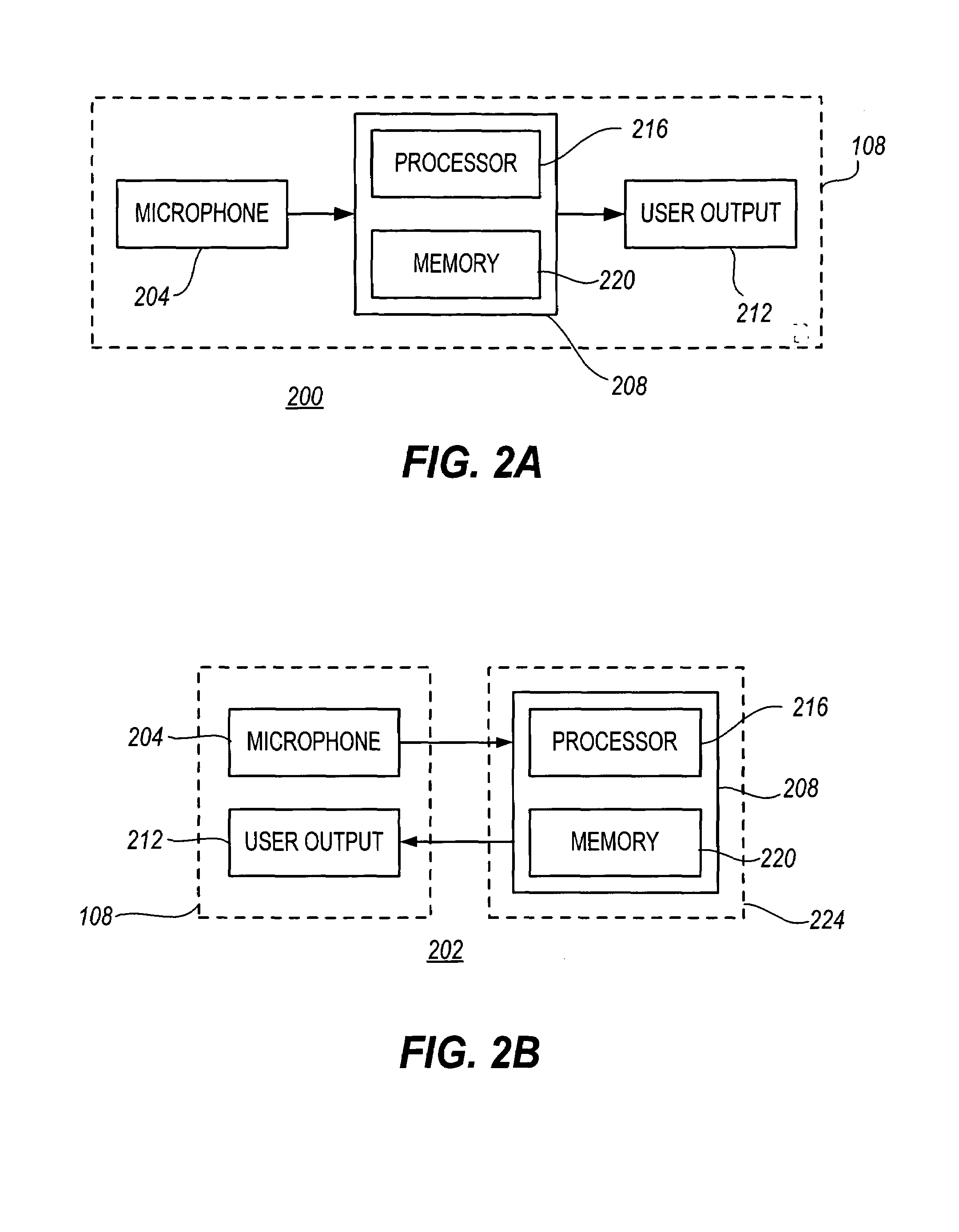
The present invention provides an indication to the user of a voice communication system that an echo at the user's location has been detected by the system. In response to receiving this indication of echo, users may take any of several actions to reduce the echo, such as changing the position of the microphone or changing their own position with respect to the microphone. The need for potentially expensive echo-canceling hardware and software is reduced because the actions to eliminate the echo are performed by the user. The echo detector in the present invention may be implemented as part of a voice terminal, or as part of a communication switch or server that is used in conjunction with a voice terminal.

Description

FIELD OF THE INVENTION[0001]The present invention is directed to providing an indication of the presence of an echo in an outgoing telephone signal. In particular, the present invention relates to providing a user with an indication that echo is present in a signal, so that a user can take appropriate action.BACKGROUND OF THE INVENTION[0002]Voice communication systems, including telephone systems, are subject to several sources of echo that make transmitted voices sound bad to listeners. These echoes can noticeably degrade the intelligibility and quality of the transmitted voice signal. One source of echo is simple acoustic reverberation at the talker's physical location. Echoes associated with acoustic reverberation at the talker's physical location are particularly evident in connection with speaker phones. However, it is often the case that people speaking into a speakerphone within small enclosed environments, such as offices or conference rooms, are unaware of such echoes.[0003...

Claims


Application Information

Patent Timeline
IPC IPC(8): H04B3/20H04M9/08
CPCH04M9/08
Inventor MICHAELIS, PAUL R.
Owner AVAYA INC
Learn More