
Stent with drug coating

Active Publication Date: 2007-01-30
ABBOTT CARDIOVASCULAR
View PDF194 Cites 188 Cited by
  • Summary
  • Abstract
  • Description
  • Claims
  • Application Information

AI Technical Summary

Problems solved by technology

A problem associated with the above procedure includes formation of intimal flaps or torn arterial linings, which can collapse and occlude the conduit after the balloon is deflated.
Vasospasms and recoil of the vessel wall also threaten vessel closure.
Yet, restenosis is still a significant clinical problem with rates ranging from 20–40%.
When restenosis does occur in the stented segment, its treatment can be challenging, as clinical options are more limited as compared to lesions that were treated solely with a balloon.
In order to provide an efficacious concentration to the treated site, systemic administration of such medication often produces adverse or even toxic side effects for the patient.

Method used


Image

  • Stent with drug coating
  • Stent with drug coating
  • Stent with drug coating

Examples


Embodiment Construction

Variable Drug Concentration or Release Rate Along the Length of the Stent

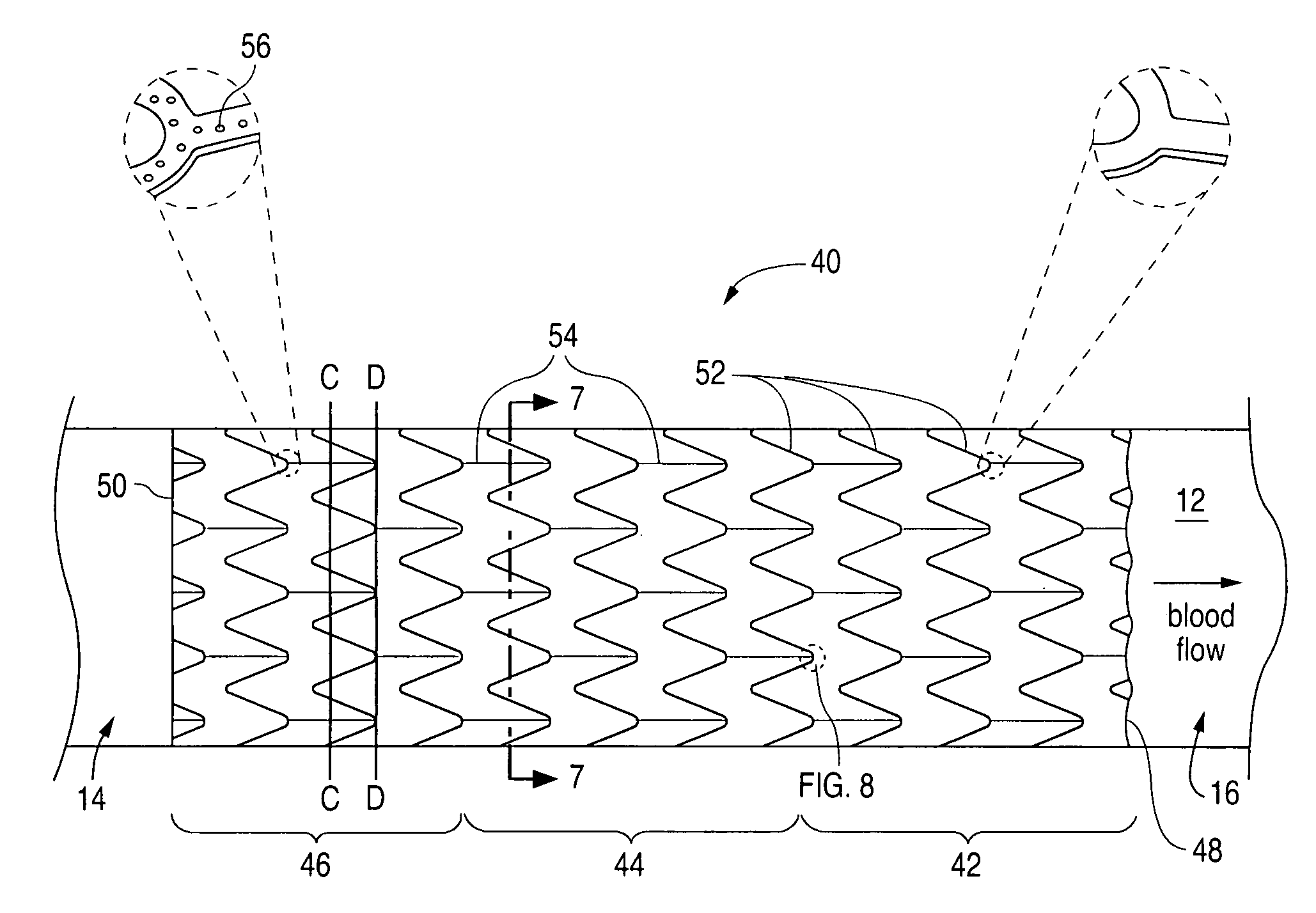
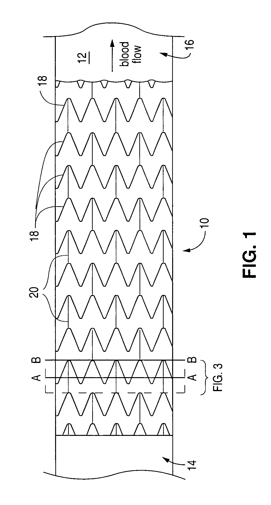
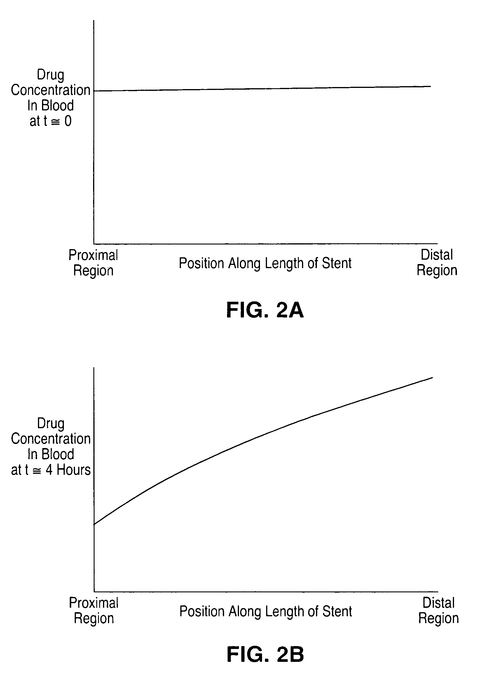
[0027]The present invention is directed to a stent with a polymeric drug coating having a variable drug concentration or release rate along the length of the stent. Referring to FIG. 4, for example, a stent 40 coated with a polymeric drug coating can have a first segment 42, a second segment 44 and a third segment 46 along the length of stent 40, disposed between a first end 48 and a second end 50. In an embodiment of the present invention, the drug concentration in the coating gradually or incrementally increases along the length of stent 40 from first end 48 to second end 50. FIG. 5, for example, graphically illustrates a drug concentration in a coating that gradually increases along the length of a stent from the distal end of stent 40 to the proximal end of stent 40. The increase of the drug concentration can also be graphically illustrated to be linear or step-wise / incremental. In another embodiment of the...


PUM


Abstract

Coatings for stents that include a polymer and a drug are provided. A method of forming the coatings is also provided.

Description

BACKGROUND OF THE INVENTION[0001]1. Field of the Invention[0002]This invention is directed to an implantable device, such as a stent, having a polymeric drug coating, and method of forming the same.[0003]2. Description of the Background[0004]Percutaneous transluminal coronary angioplasty (PTCA) is a procedure for treating heart disease. A catheter assembly having a balloon portion is introduced percutaneously into the cardiovascular system of a patient via the brachial or femoral artery. The catheter assembly is advanced through the coronary vasculature until the balloon portion is positioned across the occlusive lesion. Once in position across the lesion, the balloon is inflated to a predetermined size to remodel the vessel wall. The balloon is then deflated to a smaller profile to allow the catheter to be withdrawn from the patient's vasculature.[0005]A problem associated with the above procedure includes formation of intimal flaps or torn arterial linings, which can collapse and ...

Claims


Application Information

Patent Timeline
IPC IPC(8): A61F2/06
CPCA61F2/91A61F2/915A61F2250/0068A61F2002/91575A61F2002/91533
Inventor SANTOS, VERONICA JPRABHU, SANTOSH
Owner ABBOTT CARDIOVASCULAR
Learn More