
Reproducible, high performance patch antenna array apparatus and method of fabrication

a patch antenna array and high-performance technology, applied in the field of synthetic aperture radar patch antenna arrays, can solve the problems of large and heavy full antenna assembly, which is not easy to reproduce, and achieves the effect of reducing the size of the full antenna assembly

Inactive Publication Date: 2007-01-23
NAT TECH & ENG SOLUTIONS OF SANDIA LLC
View PDF6 Cites 24 Cited by
  • Summary
  • Abstract
  • Description
  • Claims
  • Application Information

AI Technical Summary

Benefits of technology

The invention is a patch antenna array apparatus that can be used for synthetic aperture radar (SAR) imaging applications. The apparatus is designed to be smaller, lighter, and more easily reproducible than conventional antennas. It uses a common substrate for the patch antenna and feed network, which enhances reproducibility. The apparatus has a unique geometry that reduces side-lobes and improves performance. It can be fabricated using photolithographic patterning and etching techniques. Overall, the invention provides a solution for next-generation SAR imaging applications that require high performance and reduced size, weight, and cost.

Problems solved by technology

The resulting full antenna assembly has typically been too large and heavy for next-generation applications such as those mentioned above.
Such patch antenna arrays can provide a relatively broad bandwidth capability, but do not tend to be easily reproducible.

Method used


Image

  • Reproducible, high performance patch antenna array apparatus and method of fabrication
  • Reproducible, high performance patch antenna array apparatus and method of fabrication
  • Reproducible, high performance patch antenna array apparatus and method of fabrication

Examples


Embodiment Construction

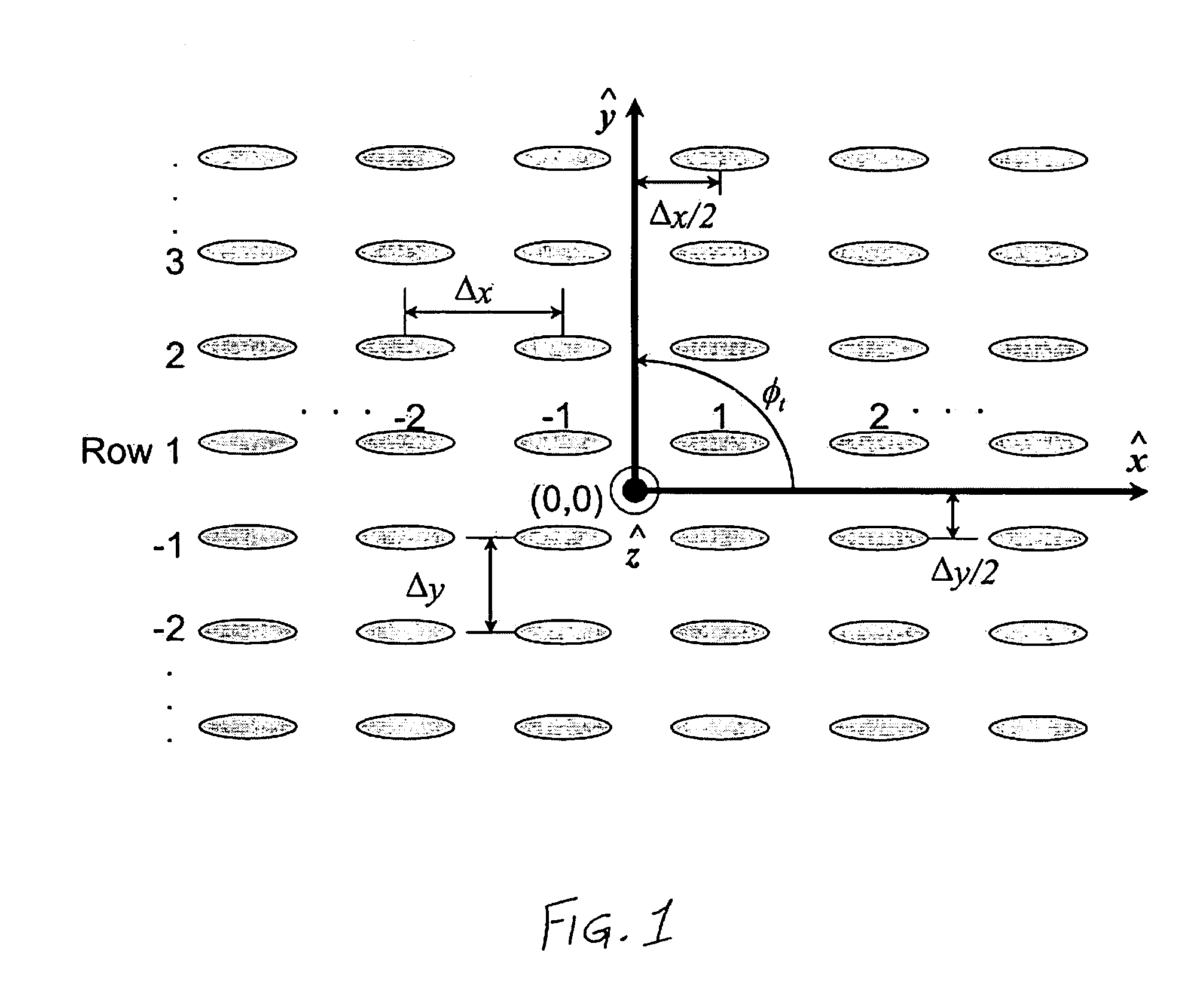
[0023]FIG. 1 graphically illustrates a two-dimensional antenna array geometry containing m columns and n rows according to exemplary embodiments of the invention. The m×n array of FIG. 1 has m=2M columns and n=2N rows, where M and N are integers. One way to achieve low side-lobes is to apply a “Hamming” weighting to taper the array's aperture. Each u,v element in the array receives power based on the amplitude weighting given by

[0024]Au,v=[2750+2350⁢cos⁡((2⁢u-(2⁢M+1)2)-12M+1⁢π)][⁢2750+2350⁢cos⁡((2⁢v-(2⁢N+1)2)-12N+1⁢π)]⁢⁢u=1,2,…⁢,mv=1,2,…⁢,n(1)

where the subscript u pertains to the uth element in {circumflex over (x)} and v identifies the vth element in ŷ. This applied aperture taper can lower the side-lobes to more than 30 dB below the main beam peak so that power is not radiated in undesirable directions. This can become a concern in applications wherein a large amount of power is transmitted. If no taper is applied to the transmitting aperture, i.e. the array has uniform weighting,...


PUM


Abstract

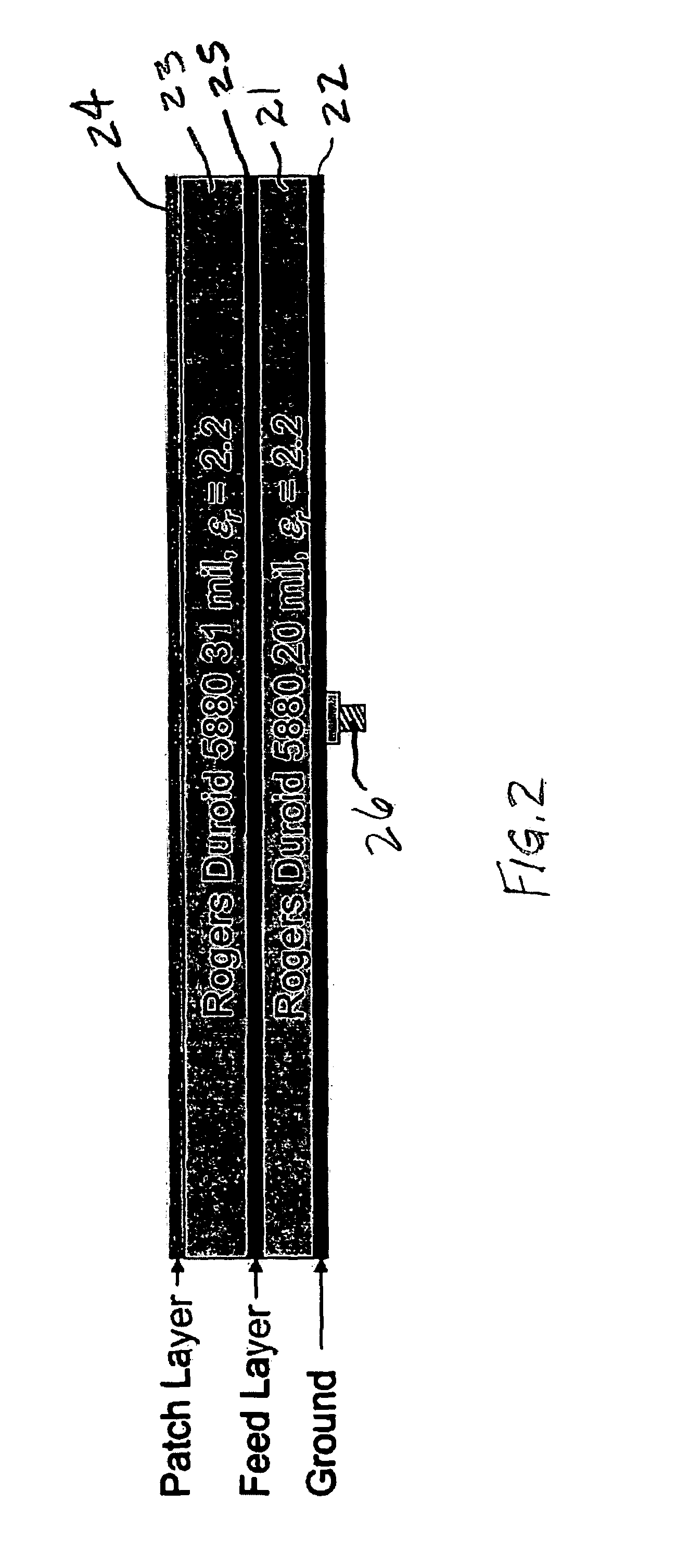
A reproducible, high-performance patch antenna array apparatus includes a patch antenna array provided on a unitary dielectric substrate, and a feed network provided on the same unitary substrate and proximity coupled to the patch antenna array. The reproducibility is enhanced by using photolithographic patterning and etching to produce both the patch antenna array and the feed network.

Description

[0001]This invention was developed under Contract DE-AC04-94AL8500 between Sandia Corporation and the U.S. Department of Energy. The U.S. Government has certain rights in this invention.FIELD OF THE INVENTION[0002]The invention relates generally to synthetic aperture radar antennas and, more particularly, to patch antenna arrays for synthetic aperture radar.BACKGROUND OF THE INVENTION[0003]The five documents listed below are incorporated herein by reference:[0004][1] C. Kidder and K. Chang, “Broad-Band U-Slot Patch Antenna With a Proximity-Coupled Double Π-Shaped Feed Line for Arrays,”IEEE Antennas and Wireless Propagation Letters, vol. 1, no. 1, pp. 2–4, 2002.[0005][2] D. H. Schaubert, “Wide-Band Phased Arrays of Vivaldi Notch Antennas,” 10th International Conference on Antennas and Propagation, no. 436, Apr. 14–17, 1997.[0006][3] W. R. Deal, N. Kaneda, J. Sor, Y. Qian, and T. Itoh, “A New Quasi-Yagi Antenna for Planar Active Antenna Arrays,”IEEE Trans. on Microwave Theory and Tech...

Claims


Application Information

Patent Timeline
Patent Type & Authority Patents(United States)
IPC IPC(8): H01Q1/38H01Q21/00
CPCH01Q9/0407
Inventor STRASSNER, II, BERND H.
Owner NAT TECH & ENG SOLUTIONS OF SANDIA LLC
Learn More