
Separation device comprising a tubular electrocoalescer

a separation device and electrocoalescer technology, applied in electrostatic separators, electrolysis, centrifugal force sediment separation, etc., can solve the problems of real risk of appearance of breakdown phenomena between electrodes and low effluent flow ra

Inactive Publication Date: 2007-01-23
INST FR DU PETROLE
View PDF5 Cites 21 Cited by
  • Summary
  • Abstract
  • Description
  • Claims
  • Application Information

AI Technical Summary

Benefits of technology

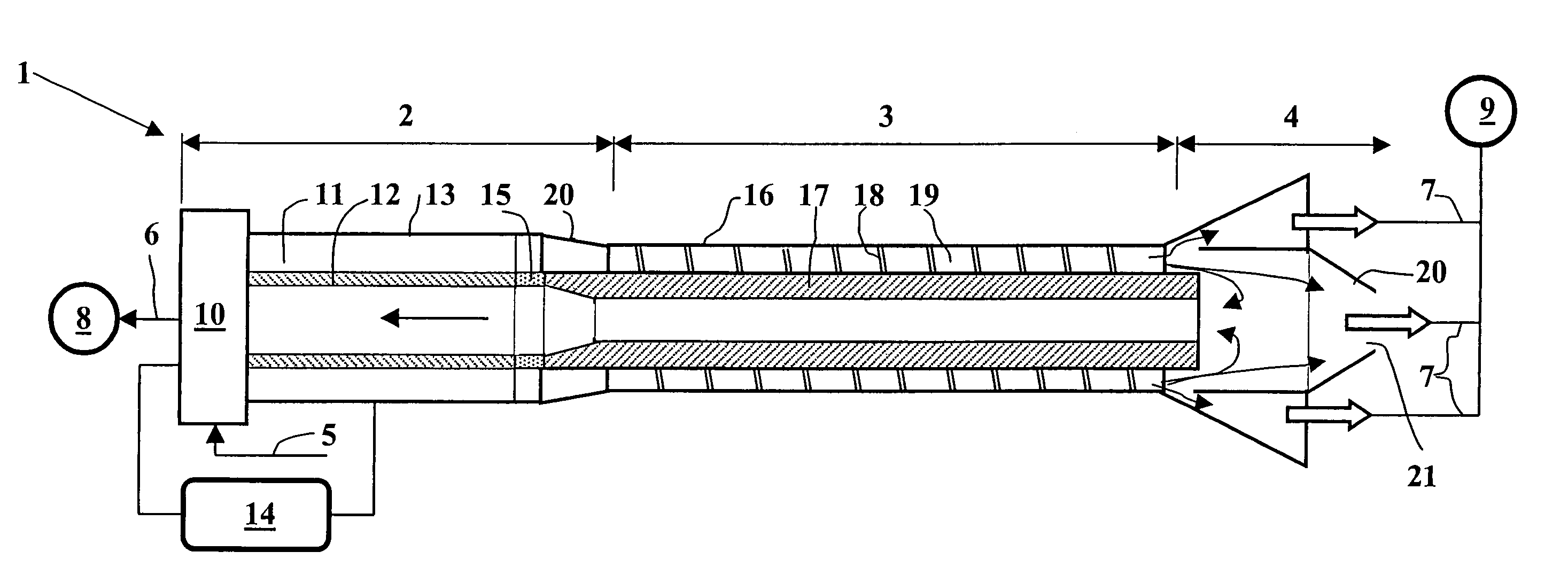
[0007]The present invention thus relates to a device for separating an effluent comprising phases of different density and conductivity. The device comprises a pair of electrodes, means for introducing the effluent between said electrodes, a helical channel in which said effluent is centrifuged, after passage between said electrodes, so that the phases are separ

Problems solved by technology

However, in order to increase the efficiency of these electrostatic separators, one tries to increase the electric potential between the electrodes, with a real risk of appearance of breakdown phenomena between electrodes.
On the other hand, considering the residence time required between the electrodes, the effluent flow rate that can be treated is low, unless an installation of disproportionate size is used.

Method used


Image

  • Separation device comprising a tubular electrocoalescer
  • Separation device comprising a tubular electrocoalescer
  • Separation device comprising a tubular electrocoalescer

Examples


Embodiment Construction

[0025]The general layout of an example of embodiment of a device according to the invention meets the following requirements:[0026]the fluid is preferably fed under pressure between two cylindrical and concentric walls, the tangential inlet is not essential but preferably maintained,[0027]the electrocoalescer has a determined geometry allowing to obtain a sufficient residence time for the effluent. For example, its length can be about 1 m and the annular space is such that the residence time of the fluid is 10 seconds at a flow rate of 500 l / h. The distance between the cylinders is therefore 7.86 mm (radius difference between a 2-inch tube (50.8 mm) and a 1-inch tube (25.4 mm)),[0028]a centrifuge is arranged after the electrocoalescer, whose motive element is one or more helical surfaces arranged between two concentric cylinders over, for example, a length of 500 mm. For information, the distance between the cylinders has been reduced to 6.35 mm (radius difference between a 1.5-inch...


PUM

PropertyMeasurementUnit
Angleaaaaaaaaaa
Angleaaaaaaaaaa
Electrical conductivityaaaaaaaaaa

Abstract

The present invention relates to a device for separating an effluent comprising phases of different density and conductivity, the device comprising a pair of electrodes (12, 13), means (10) for introducing the effluent between said electrodes, means intended for separation (3) and discharge (4) of said separated phases. The separation means comprise at least one centrifugation element including a helical channel (19) in which the effluent is centrifuged after passing between the electrodes. An opening extends over the entire periphery of said centrifuged effluent so as to discharge part of the centrifuged effluent. The discharge means further comprise sealing means for limiting discharge of the less dense phase through said opening.

Description

FIELD OF THE INVENTION[0001]The present invention relates to the field of emulsified effluent processing, notably petroleum effluents from production wells. The emulsions concerned are those whose disperse phase is electrically conducting, unlike the continuous phase, for example water dispersed in an organic phase such as oil.[0002]It is important to separate the water from the effluent produced so as to improve the quality, therefore the market value, of the effluent and to limit the size of the processing and transport equipments. After passage of the emulsified effluent through conventional water / oil separators, the effluent still contains about 1 to 5% emulsified water in the oil. The goal of the present invention is to decrease these residual amounts of water and salts in order to meet the technical requirements of the downstream processes.BACKGROUND OF THE INVENTION[0003]Document U.S. Pat. No. 5,647,981 describes a device which combines the principle of an electrocoalescer wi...

Claims


Application Information

Patent Timeline
IPC IPC(8): B04B5/10B01D17/038B03C5/02B01D1/00B01D17/02B01D17/06B04B11/00B04C5/181B04C9/00
CPCB01D17/0217B03C11/00B01D17/045B01D17/06B04C5/181
Inventor TRAPY, JEANNOIK, CHRISTINE
Owner INST FR DU PETROLE
Learn More