
Modular pack system with belt and leg bags

Inactive Publication Date: 2007-01-23
SUMMIT OUTDOOR PROD LLC +1
View PDF12 Cites 20 Cited by
  • Summary
  • Abstract
  • Description
  • Claims
  • Application Information

AI Technical Summary

Benefits of technology

[0009]1. Lowering the center of gravity of the bag assembly on the loaded user, so that the user is not so top-heavy and off-balance.
[0025]The inventor envisions a wide assortment of bags and attachable devices for cooperation with the belt. As mentioned above, small, medium, and large bags are available, as well as bags of differing materials, such as woven material, waterproof material, or mesh bags, for example. Mesh bags may be particularly attractive to those who will be in water and do not want: 1) air-holding bags to possibly become a problem by making the user's lower body more buoyant than his / her upper body, or 2) bags to fill with water and reduce the buoyancy of the user.

Problems solved by technology

The technique of carrying supplies / equipment in a backpack has many drawbacks, however.
The backpack moves the user's center of gravity upwards and backwards, which tends to throw the user off-balance and makes many activities clumsy, difficult, and sometimes even dangerous.
The backpack attaches a large, weighty object in back of the user, which, when the user is moving quickly, can create unpredictable forces on the user.
For example, wearing a backpack while climbing or hiking over steep or difficult terrain greatly increases the chance of the user falling.
Further, the pleasure of hiking, running, climbing, biking, horseback riding, and other activities is diminished if the user must be more conscience of his motions and his balance due to a backpack.
The present inventor believes the angular, rectangular, and thick shape of the Clem device would cause discomfort to the user's leg and would cause discomfort to the user's arm when the arm swings back and forth, thus making any but the most sedentary use impractical and uncomfortable.

Method used


Image

  • Modular pack system with belt and leg bags
  • Modular pack system with belt and leg bags
  • Modular pack system with belt and leg bags

Examples


Embodiment Construction

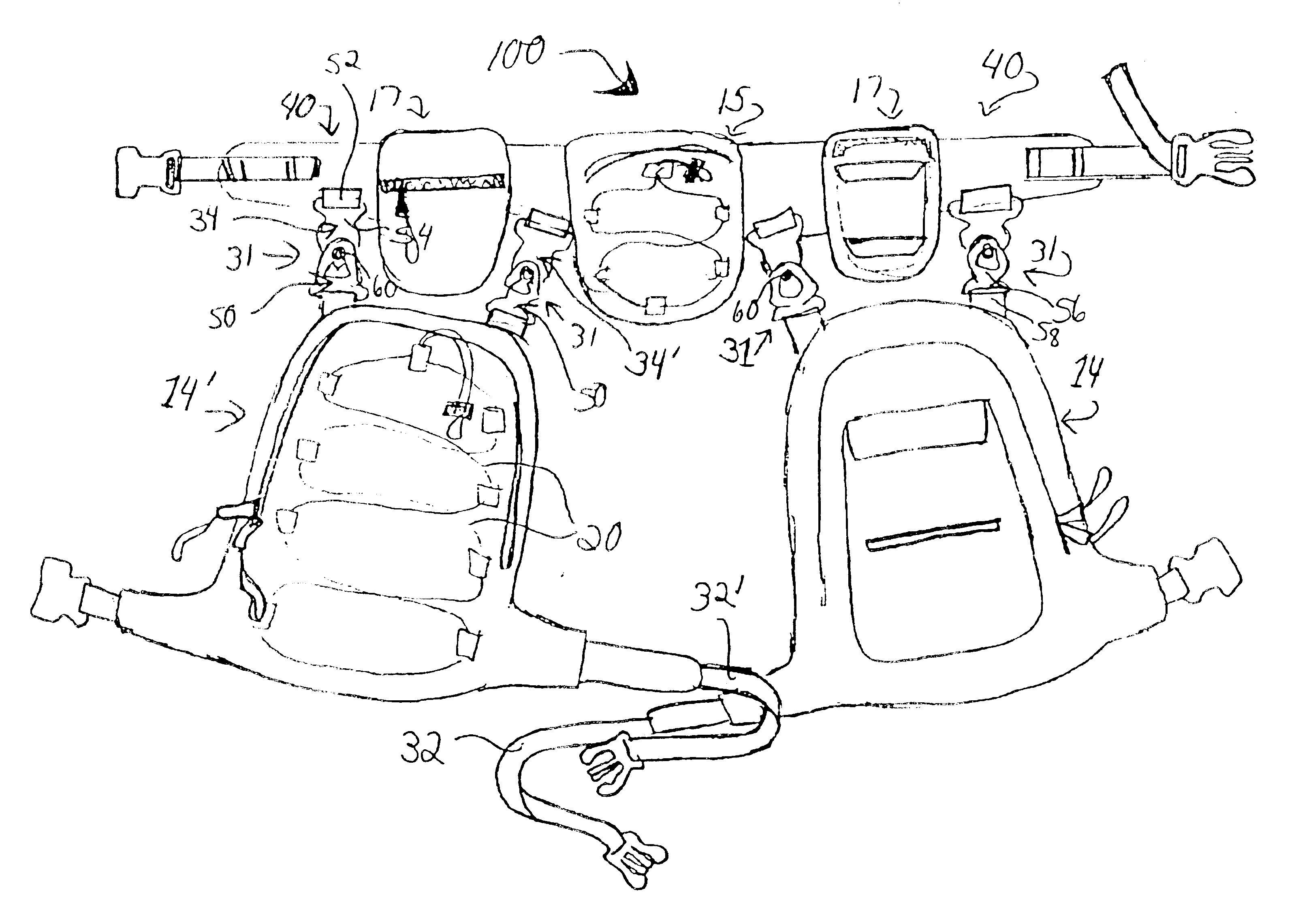
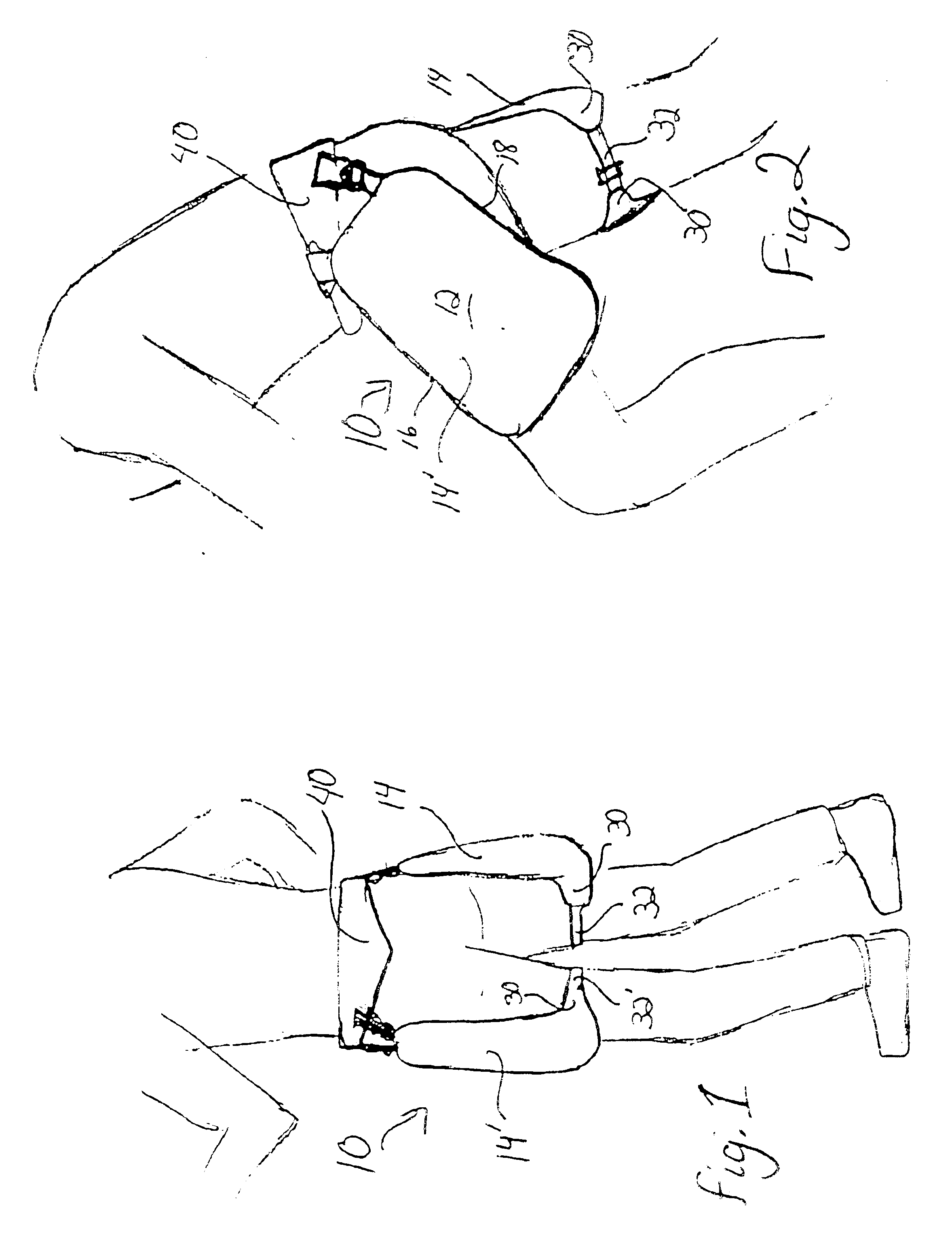
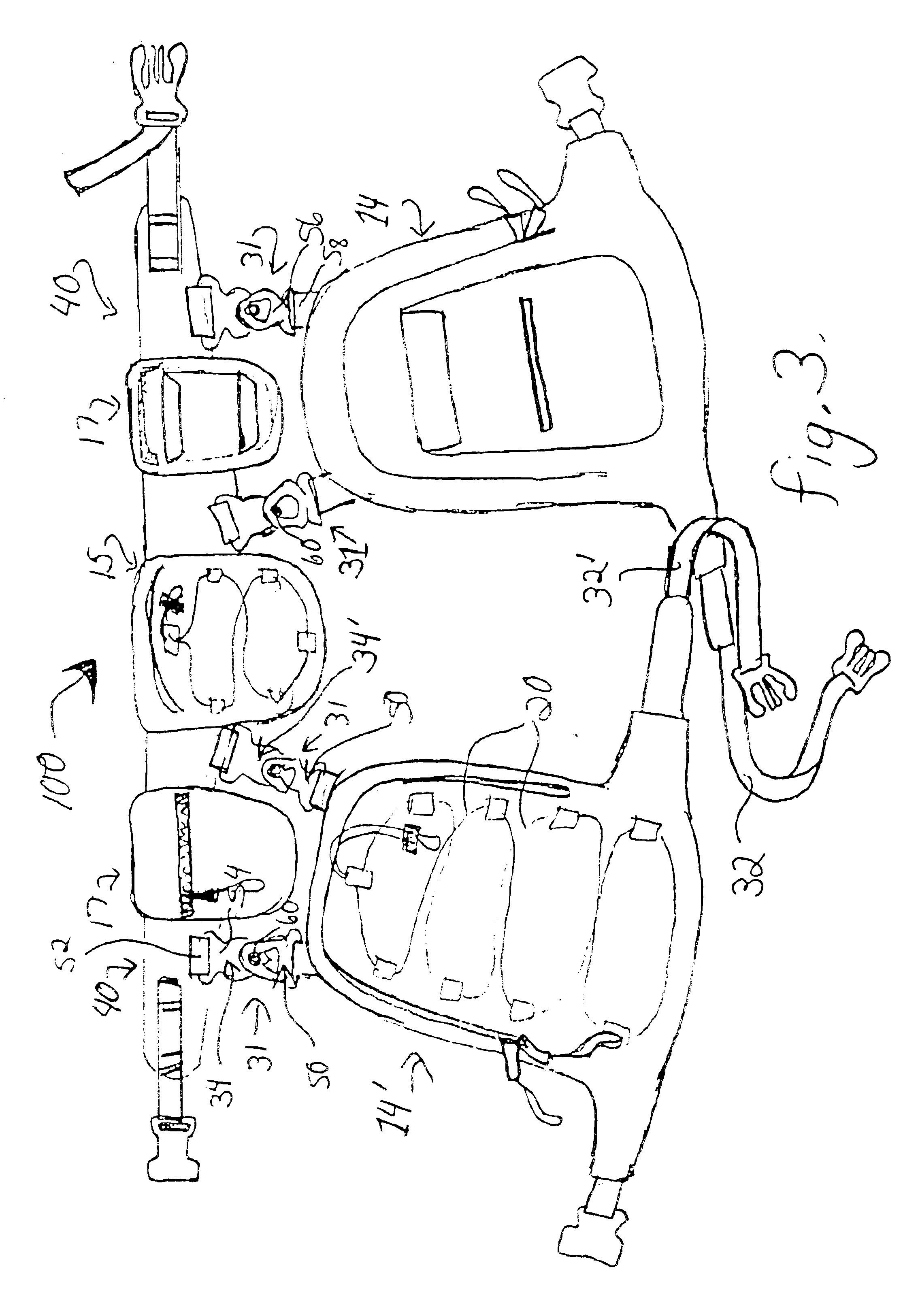
[0046]Referring to the drawings, there are shown preferred, but not the only, embodiments of the invented leg pack system 10. Preferably, the leg pack system includes bags and carried objects that are positioned substantially between the waist and the knee, and not below the knee. Preferably, the leg pack system includes bags and carried objects at both sides of the user, substantially equally distributed between right and left side, and optional small bags and objects on the back or the front.

[0047]As illustrated in FIG. 1, a preferred modular leg pack system 10 comprises a right thigh bag 14 and left thigh bag 14′, on a hip belt 40 that is fastened around the user's waist or upper hips. The thigh bags 14, 14′ extend from a few inches below the belt to a few inches above the knees, and wrap part way around the legs. Each bag has a strap 32, 32′ fastened around the leg above the knee, with the leg strap 32, 32′ fasteners easily reachable by the user from the front.

[0048]FIG. 2 illus...


PUM


Abstract

A modular leg pack system is shown and described, embodiments of which include a belt or belt sleeve for wearing around the body, and preferably at the top of the hips, and preferably two thigh opposing bags. The thigh bags extend from just below the belt to above the knee. One or more top connectors attach the top of the bag to the belt, and a bottom leg strap extends from the bottom of the bag around the inside of the leg. To assist in natural movement of the bag with the leg, the preferred top connectors have a pivot point that allows the bag to pivot in a direction parallel to the motion of the leg. Additionally, it is preferred to have the top connector rotatable relative to the belt in a plane perpendicular to the outer surface of the belt, and rotatable relative to the bag in a plane perpendicular to the back plane of the bag. Openings of the bags are positioned to be easily accessible by the user, usually on the top of the bag.

Description

[0001]This application claims priority of prior, co-pending application Ser. No. 60 / 224,445, filed Aug. 10, 2000, which is herein incorporated by this reference.BACKGROUND OF THE INVENTION[0002]1. Field of the Invention[0003]Generally, the invention relates to packs for recreational, sport, hunting, and exercise use, which are used to carry supplies or possessions that are needed on a hike, ride, walk, horseback ride, etc. More specifically, the invention relates to a leg pack system that includes bags that are positioned near and connected to the legs of the user. Preferably, the bags hang from a waist belt along the outside of the user's thigh, and extend between the belt and the user's knee.[0004]2. Related Art[0005]Many back packs have been developed for carrying equipment, food, and personal items during hiking, walking, climbing, and other outdoor sports and recreational activities. The term “backpacking” has become nearly synonymous with hiking while carrying supplies and equ...

Claims


Application Information

Patent Timeline
IPC IPC(8): A45F3/00A45C7/00A45C13/10
CPCA45C7/009A45F3/00A45F5/021A45C13/10Y10S224/904A45F2003/002A45F2003/008
Inventor BARR, JARROD
Owner SUMMIT OUTDOOR PROD LLC
Learn More