
AC power line impedance monitoring method and system

a technology of impedance monitoring and power line, applied in the direction of resistance/reactance/impedence, measurement of impedence, instruments, etc., can solve the problems of high imprecise techniques, unwanted conditions can arise in loads, distribution equipment and lines, etc., and achieves high imprecise or incomplete techniques. still somewhat imprecise or incomplete

Active Publication Date: 2007-01-16
ROCKWELL AUTOMATION TECH
View PDF17 Cites 25 Cited by
  • Summary
  • Abstract
  • Description
  • Claims
  • Application Information

AI Technical Summary

Benefits of technology

The present invention provides new techniques for measuring the impedance of power lines. These techniques can be used in various settings such as energy determination, identifying short circuit currents, and identifying possible problems with under-loading of power lines. The techniques can be implemented in both permanent and mobile devices and can use analog or digital circuitry. The invention involves measuring the voltage waveform through the power line and identifying the inductive and resistive components of the power line impedance. These identifications can then be used for further processing or estimations.

Problems solved by technology

For example, in many application unwanted conditions can arise in loads, distribution equipment and lines, the severity of which is a function of the line impedance.
However, such techniques are highly imprecise, and rely upon some degree of estimation as to the actual characteristics of the components and transmission lines.
Such techniques have permitted some degree of knowledge of the power line impedance, but are still somewhat imprecise or incomplete.
For example, known techniques do not typically permit measurement of both inductive and resistive components of the power line impedance.

Method used


Image

  • AC power line impedance monitoring method and system
  • AC power line impedance monitoring method and system
  • AC power line impedance monitoring method and system

Examples


Embodiment Construction

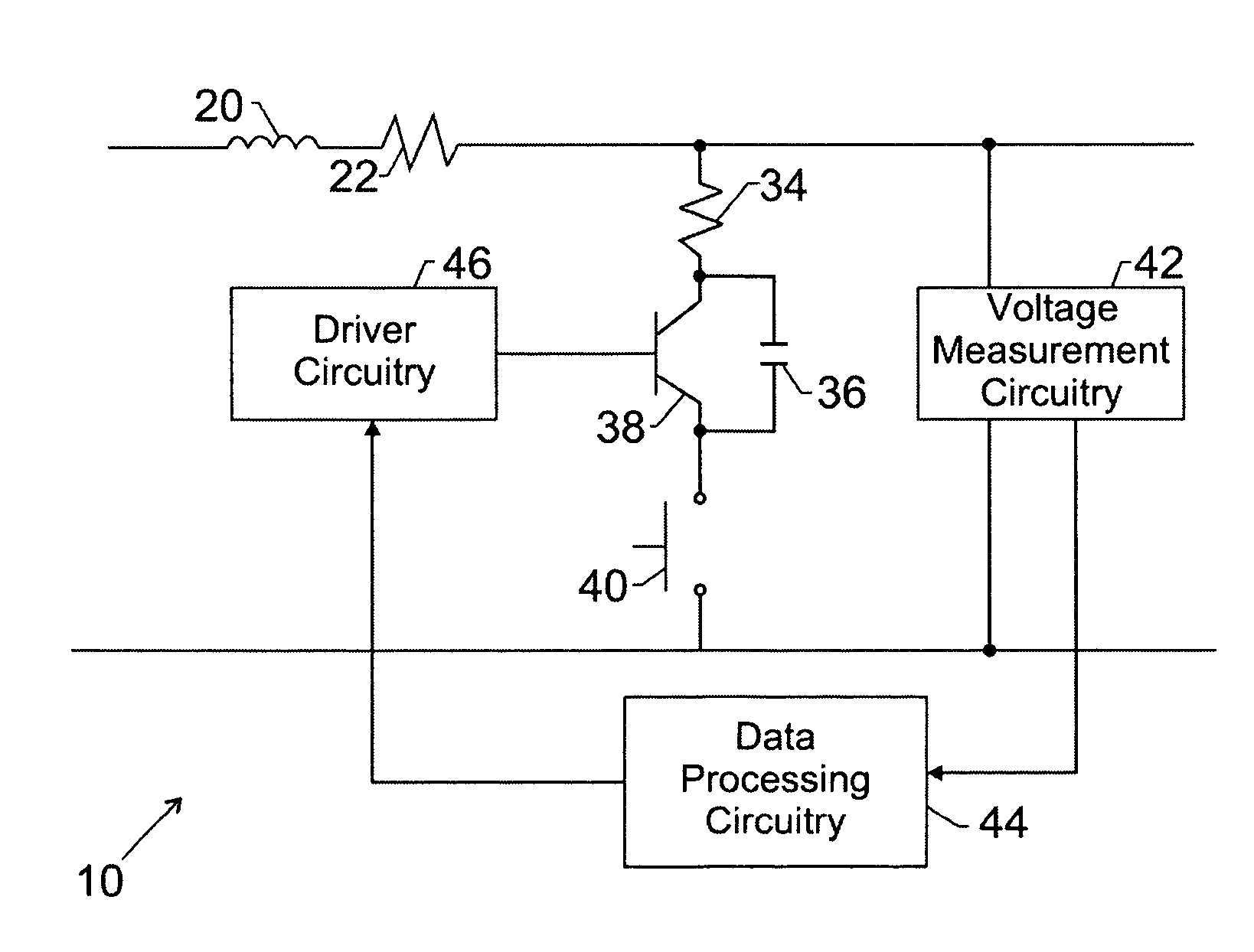
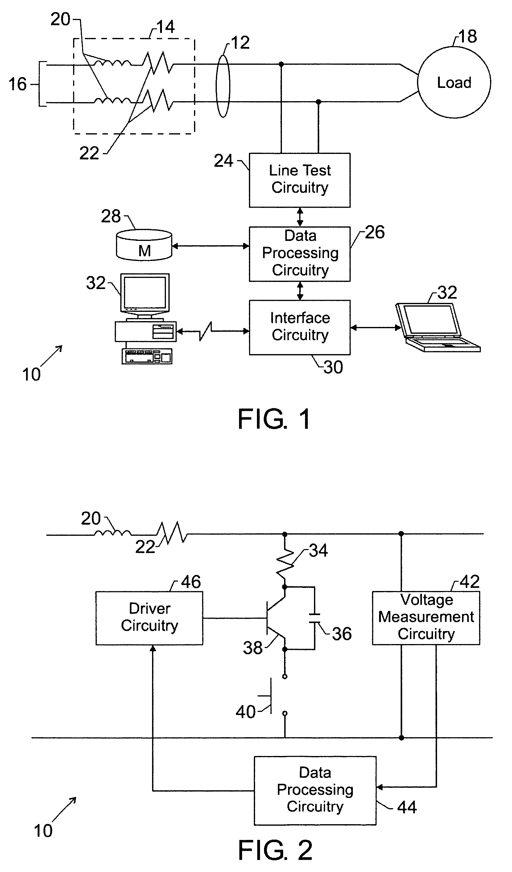
[0018]Turning now to the drawings, and referring first to FIG. 1, an impedance monitoring system is illustrated and designated generally by the reference numeral 10. The impedance monitoring system is illustrated in a single-phase application. That is, the system is illustrated for identifying the impedance of a single-phase power source. As will be appreciated by those skilled in the art, and as discussed in greater detail below, the system may be easily adapted for identifying impedance parameters of three-phase power lines and sources as well.

[0019]Impedance monitoring system 10 is illustrated as coupled to a pair of power supply lines 12. Power supply lines 12, and any upstream circuitry, such as transformers, connectors, and so forth are considered to have a net impedance illustrated by equivalent circuitry in box 14 of FIG. 1. The impedance 14 is, for the present purposes, considered to be a collective or cumulative impedance of the entire power supply network, represented gen...


PUM


Abstract

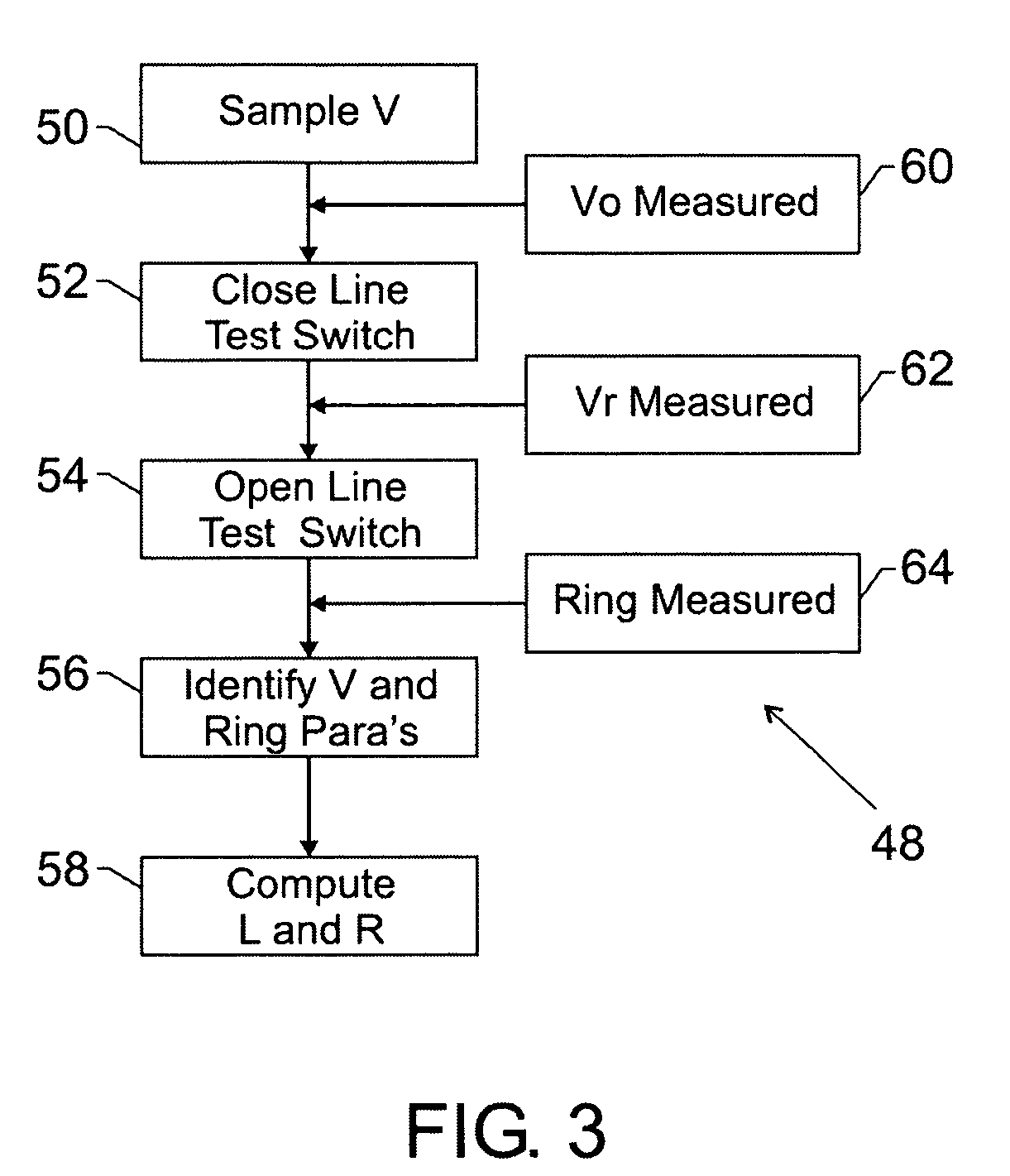
A technique for determining inductive and resistive components of power line impedance. A measurement circuit switches a burden or drain resistor between power line conductors to cause a droop or sag in a voltage waveform. The voltage waveform is sampled prior to inclusion of the resistor in the circuit, as well as after to identify the droop. The short circuit between the power lines is then removed by opening the circuit and a capacitor in the test circuitry causes a resonant ring due to the inductive component of the power line impedance. Based upon the period or frequency of the resonant ring, and upon the voltage measurements with and without the resistor in the circuit, the inductive and resistive components of power line impedance can be computed.

Description

BACKGROUND[0001]The present invention relates generally to the field of monitors and measurement devices for electrical power. More particularly, the invention relates to techniques for determining impedance parameters of electrical power, particularly power distributed via a power distribution grid.[0002]A wide range of applications exists for power monitors and devices capable of determining parameters of electrical power. For example, in many application unwanted conditions can arise in loads, distribution equipment and lines, the severity of which is a function of the line impedance. For example, the line impedance is a precursor to calculating short circuit current, arc current, available energy, and other important features of electrical power. Because these currents and energies can flow or be released during a fault condition or other unwanted, or even desired situations, knowing the power line impedance is of considerable importance.[0003]Various methods exist in the art fo...

Claims


Application Information

Patent Timeline
Patent Type & Authority Patents(United States)
IPC IPC(8): G01R27/28G01R27/08
CPCG01R27/16
Inventor GASPERI, MICHAEL LEE
Owner ROCKWELL AUTOMATION TECH
Learn More