


Quick Research
Generate reliable direction feasibility study reports for your R&D in just a few steps.

Technical Q&A
Discover and master advanced knowledge NOW. Basics, ideas, possibilities, all at once.

Find Solutions
As an expert in R&D theories, this can generate solutions to your technical problems instantly.

Evaluate Feasibility
Analyze your overall solution with one click, know your potential R&D risks in advance.

Monitor Landscape
Get weekly tech updates, stay abreast of the latest tech innovations and key insights.
Small zoom lens, and digital camera and video camera both having same
a technology of zoom lens and digital camera, applied in the field of small zoom lens, can solve the problems of reducing the curvature of the lens surface with decreasing refractive power, unable to perform aberration correction in sufficient degree, and reducing the refractive power of the third lens group. , to achieve the effect of high image quality
- Summary
- Abstract
- Description
- Claims
- Application Information
AI Technical Summary
Benefits of technology
Problems solved by technology
Method used
Image


Examples
embodiment 1
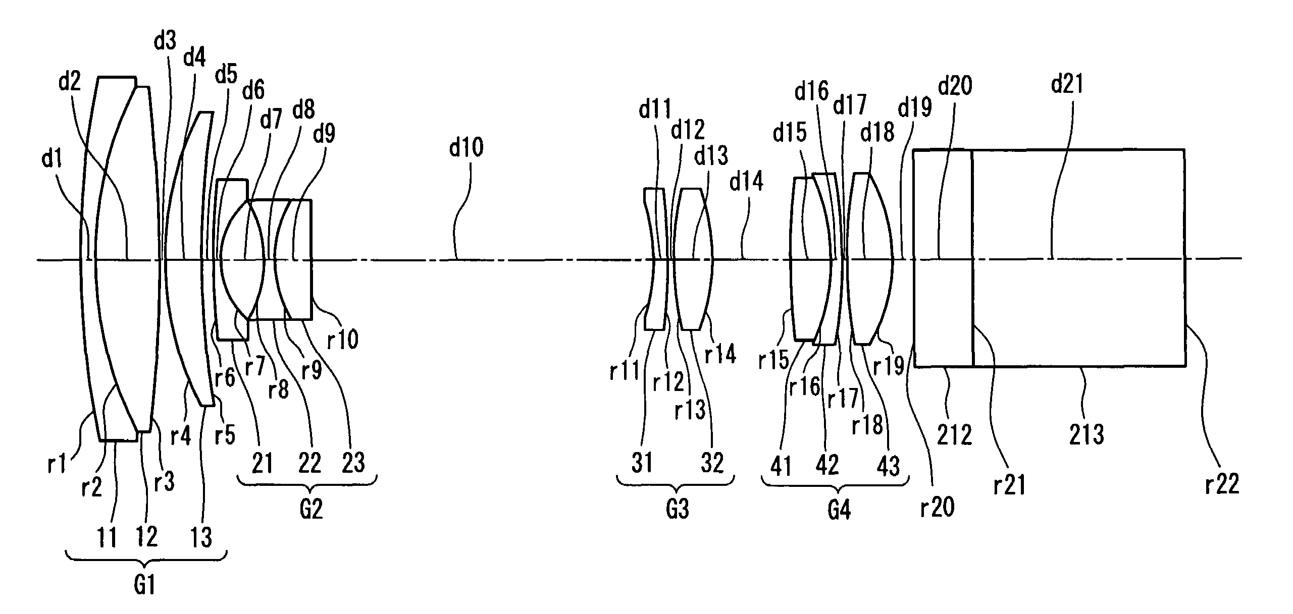
[0072]FIG. 1 shows the configuration of a small zoom lens according to Embodiment 1 of the present invention.
[0073]The small zoom lens according to this embodiment is provided with a first lens group G1, a second lens group G2, an aperture stop (not shown), a third lens group G3 and a fourth lens group G4, arranged in that order from the object side.
[0074]The first lens group G1 includes a lens 11 having a negative refractive power, a lens 12 having a positive refractive power and a lens 13 having a positive refractive power, arranged in that order from the object side, has a positive refractive power as a whole, and is fixed with respect to the image plane.
[0075]The second lens group G2 has a negative refractive power as a whole, and causes a zooming action when moved along the optical axis. The second lens group G2 includes at least one aspherical surface, and includes a meniscus negative lens 21 whose convex surface faces the object side, a lens 22 having a negative refractive po...
working example 1
[0081]In the following, Table 1 shows a specific numerical example of a zoom lens according to Working Example 1, which corresponds to Embodiment 1. In Table 1, r represents the curvature radius of the lens surfaces, d represents the lens thickness or the air space between the lenses, n represents the refractive index of the lenses for the d-line, and v represents the Abbe number of the lenses for the d-line.
[0082]Table 2 shows the aspherical coefficients of the lens surfaces constituting the aspherical surfaces. Each of the aspherical surfaces has a rotationally symmetric aspherical surface shape represented by the following equation:
[0083]SAG=H2 / R1+1-(1+K)(H / R)2+D·H4+E·H6+F·H8+G·H10
where, SAG represents the amount of displacement of the lens surface at the point apart from the optical axis by the height H in the radical direction with respect to the lens apex, R represents the curvature radius, K represents the conical constant, and D, E, F and G represent the aspherical coeffici...
working example 2
[0091]In the following, Table 4 shows a specific numerical example of a zoom lens according to Working Example 2, which corresponds to Embodiment 1. Table 5 shows the aspherical coefficients of the lens surfaces constituting the aspherical surfaces. Table 6 shows the values of the variable air space at various zooming positions, when zooming is performed for a given object point located at infinity, measured from the tip of the lens.
[0092]
TABLE 4groupsurfacerdnν1 145.7470.651.8466623.9 218.4363.101.6031160.7 3−60.1320.15 414.0231.801.7725049.6 532.850var.2 632.8500.401.8830040.9 74.3651.98 8−6.5560.501.6654755.2 95.3861.801.8466623.910−44.614var.311−10.0000.551.6968055.612−80.0000.201313.1471.451.6060257.414−18.722var.41527.2572.001.4874970.416−9.7180.451.8466623.917−30.7430.201814.8371.951.5145063.119−8.513var.520∞2.301.5163364.121∞11.00 1.5891361.222∞−
[0093]
TABLE 5sur-face8131819K−3.86106E+000.00000E+000.00000E+000.00000E+00D−1.88746E−03−4.02222E−04−1.90832E−044.51829E−04E7.81554E...
PUM
 Abstract
Description
Claims
Application Information
 - R&D Engineer
- R&D Manager
- IP Professional
- Industry Leading Data Capabilities
- Powerful AI technology
- Patent DNA Extraction
Browse by: Latest US Patents, China's latest patents, Technical Efficacy Thesaurus, Application Domain, Technology Topic, Popular Technical Reports.
© 2024 PatSnap. All rights reserved.Legal|Privacy policy|Modern Slavery Act Transparency Statement|Sitemap|About US| Contact US: help@patsnap.com