Coolant feed drill nozzle with thrust-vectored exhaust

a drill nozzle and thrust-vectored technology, which is applied in the direction of large fixed members, manufacturing tools, transportation and packaging, etc., can solve the problems of not allowing coolant injection towards the drill bit, dangerous, inconvenient, time-consuming process, etc., and achieves high-quality holes.

Inactive Publication Date: 2007-01-09
THE BOEING CO
View PDF16 Cites 9 Cited by
  • Summary
  • Abstract
  • Description
  • Claims
  • Application Information

AI Technical Summary

Benefits of technology

[0007]The present invention provides a drill nozzle that can be attached to a drill motor unit and that allows coolant injection towards a drill bit during the drilling operation while vacuum extracting the drilling debris at the same time, such that no chips, dust, or remaining coolant fluid may exit the drill nozzle towards the drill motor unit. The present invention further provides a drill nozzle that is suitable for, but not limited to, being attached to a drill motor unit of a prior art numerically controlled drill jig, enabling the use of such numerically controlled drill jig for drilling high quality holes effectively into non-flat surfaces, for example, the leading edge extension spar of the F-18 aircraft. The present invention still further provides a method for providing coolant to a drill bit during the drilling process on non-flat surfaces while vacuum extracting the drilling debris, such that no drilling debris may damage or spoil the drill motor unit, to which the drill nozzle of the present invention may be attached, or any surrounding structures and surfaces.
[0012]In still another aspect of the present invention, a method for providing coolant to a drill bit and for vacuum extracting drilling debris generated during a drilling process on non-flat surfaces comprises the steps of: providing a drill motor unit including a drill bit; providing a drill nozzle including: a housing having an air intake, multiple coolant inlets, multiple coolant passageways, multiple coolant jets, a vacuum tube, and mounting flanges; and a bristle brush ring attached to the housing; attaching the drill nozzle to the drill motor unit using the mounting flanges; providing pressurized air to the air intake and creating a thrust-vectored down draft into the vacuum tube; providing coolant fluid through the coolant inlets and through the coolant passageways toward the coolant jets; expelling coolant fluid onto the drill bit; providing suction to the vacuum source; drilling a hole into a non-flat surface and generating drilling debris; vacuum extracting the drilling debris trough the vacuum tube; preventing drilling debris from exiting the housing of the drill nozzle towards the drill motor unit by providing the thrust-vectored down draft; containing the drilling debris and coolant fluid inside the bristle brush ring, wherein the bristle brush ring touches the non-flat surface; and preventing damaging and soiling surrounding structures and surfaces with the bristle brush ring.

Problems solved by technology

Although the numerically controlled drill jig enables simple and low cost automation of the manufacturing process, the drill head unit of this system can only be used on the skins of the aircraft.
However, manually applying the coolant to the drill bit and manually vacuum extracting the drilling debris is a dangerous, inconvenient, and time-consuming process.
Even though these patents describe devices for vacuum extraction of drilling debris, for example, chip swarf and dust particles, these devices either don't allow coolant injection towards the drill bit (U.S. Pat. No. 5,988,954 and U.S. Patent application No.
U.S. Pat. No. 6,200,075 B1) or these devices are too complex and not suitable to address the needs described above.
These prior art devices comprise attachments to a drill motor but do not provide coolant injection towards a drill bit or vacuum extraction of the drilling debris during the drilling process.
Further, these prior art devices are not suitable for the use on non-flat surfaces, for example, the leading edge extension spar of the F-18 aircraft, to address the needs described above.

Method used


Image

  • Coolant feed drill nozzle with thrust-vectored exhaust
  • Coolant feed drill nozzle with thrust-vectored exhaust
  • Coolant feed drill nozzle with thrust-vectored exhaust

Examples


Embodiment Construction

[0026]The following detailed description is of the best currently contemplated modes of carrying out the invention. The description is not to be taken in a limiting sense, but is made merely for the purpose of illustrating the general principles of the invention, since the scope of the invention is best defined by the appended claims.

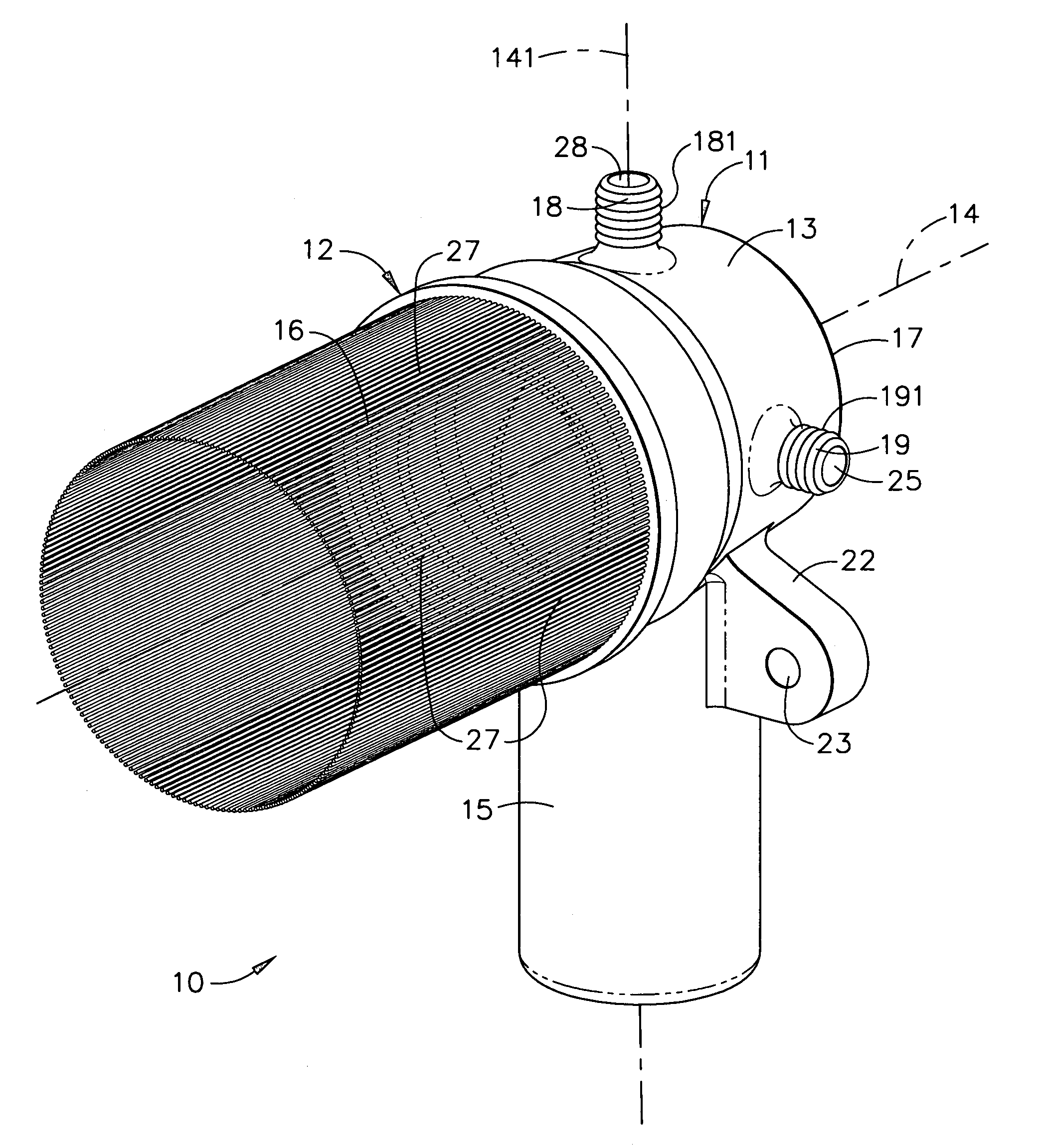
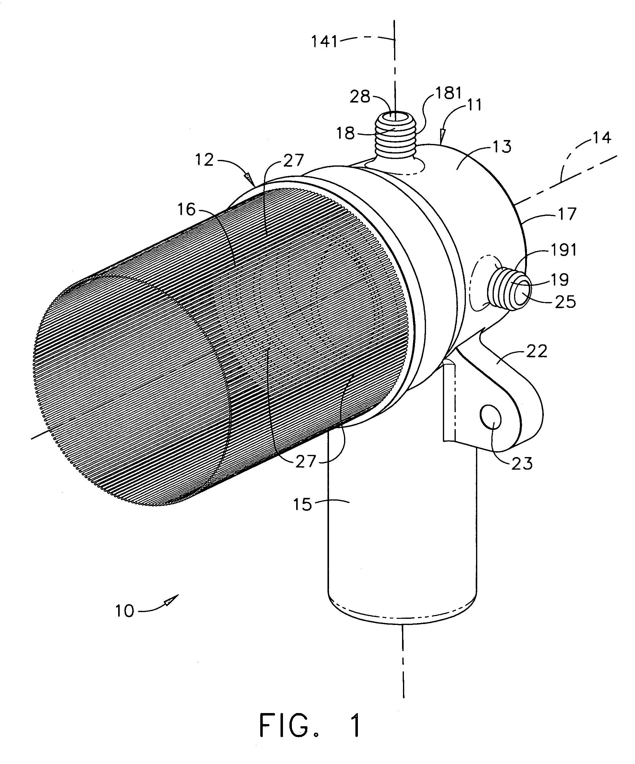
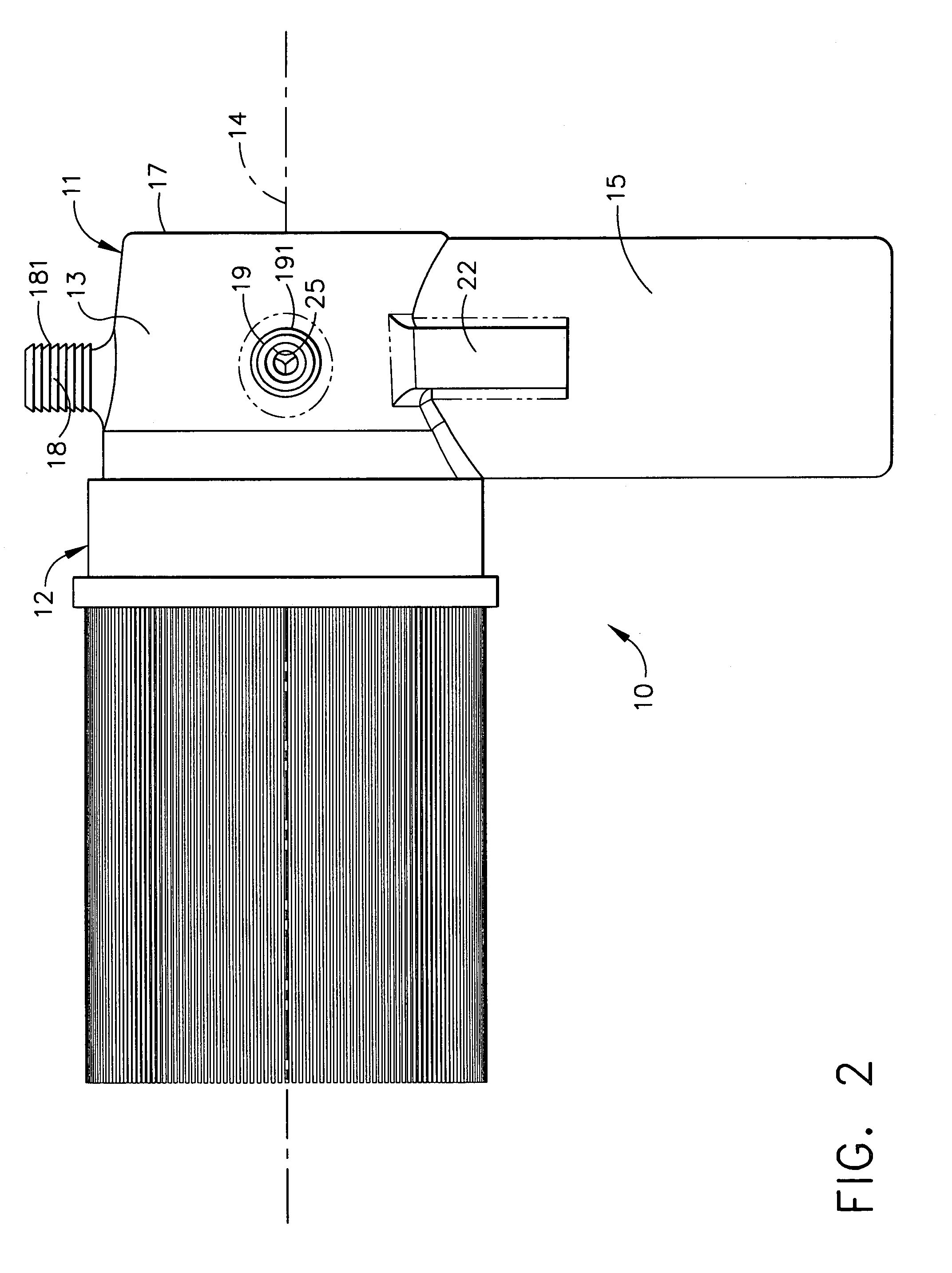
[0027]Broadly, an embodiment of the present invention provides a drill nozzle suitable for drilling into non-flat surfaces. The drill nozzle according to an embodiment of the present invention may be attached to a drill motor unit, and therefore, eliminates the dangerous manual operation of the coolant and vacuum processes of the prior art. An embodiment of the present invention also provides a drill nozzle that allows coolant injection towards a drill bit during the drilling operation on non-flat surfaces while vacuum extracting the drilling debris at the same time such that no chips, dust, or remaining coolant fluid may exit the drill nozzle towards t...


PUM

PropertyMeasurementUnit
cylindrical shapeaaaaaaaaaa
shapeaaaaaaaaaa
outer diameteraaaaaaaaaa

Abstract

A drill nozzle includes a housing having a bristle brush ring attached. The housing of the drill nozzle may include an air intake, multiple coolant inlets, multiple coolant jets, a vacuum tube, and mounting flanges. The air intake may provide a thrust-vectored down draft into the vacuum tube. The coolant inlets may receive coolant fluid that may be expelled from the coolant jets towards a drill bit. Drilling debris and coolant fluid may be contained inside the bristle brush ring preventing damage and soiling of surrounding structures and areas and may be extracted with the vacuum tube. The drill nozzle may be attached to a drill motor unit of a numerically controlled drill jig, enabling the use of such numerically controlled drill jig for drilling high quality holes effectively into non-flat surfaces, for example, the leading edge extension spar of the F-18 aircraft.

Description

BACKGROUND OF THE INVENTION[0001]The present invention generally relates to devices that can be attached to a drill motor and methods for providing coolant to a drill bit and for chip extraction during a drilling process and, more particularly, to a coolant feed drill nozzle with a thrust-vectored intake and a method for providing coolant to a drill bit and for vacuum extraction of drilling debris during drilling on non-flat surfaces.[0002]Advanced aircraft, for example, the F-18, require many holes to be drilled into the fuselage of the aircraft. A numerically controlled drill jig exists for use on the forward fuselage of an F-18 aircraft. The numerically controlled drill jig offers an ergonomic, portable, foundation-free system for drilling holes into the skin of the aircraft that easily adapts to changes in the fabrication process while improving hole quality. This system utilizes a drill head unit that provides pressure to the fuselage skin of an aircraft, injects coolant toward...

Claims


Application Information

Patent Timeline
Patent Type & Authority Patents(United States)
IPC IPC(8): B23B47/34B23Q11/10B23B35/00B23Q11/00
CPCB23Q11/0046Y10T408/50Y10T409/304032Y10T408/46Y10T408/03Y10T409/304088Y10T408/44B33Y80/00
Inventor WOOD, JEFFREY H.SITTON, KEVIN J.
Owner THE BOEING CO
Why Eureka
Try Eureka