
Device for obtaining a predefined linear force

a linear force and predetermined technology, applied in the direction of resistance force resistors, muscle exercising devices, sport apparatus, etc., can solve the problems of limiting the freedom of speed and acceleration selection, unavoidable acceleration of mass, and inability to perform during weight training or weight-based training equipmen

Inactive Publication Date: 2007-01-02
PLAVSIC VOJIN
View PDF8 Cites 3 Cited by
  • Summary
  • Abstract
  • Description
  • Claims
  • Application Information

AI Technical Summary

Benefits of technology

[0017]As regards training, the constant force / torque provided by the present invention gives anatomically and physiologically natural desirable combinations of muscle load forces and the derivates (speeds or accelerations) of the muscle contraction length, which combinations are preferably easily pre-set. The device according to the invention enables a controlled and regular training of a given muscle strength. Further the device according to the invention is extremely effective for training of the explosive muscle strength, which is very important for top athletes. It is accomplished by allowing the muscles to contract with a given or maximum acceleration or speed with a given muscle load. Thereby a widened area of use is obtained from rehabilitation to body-building and competition sport.
[0018]Further the present invention can provide a totally mechanical device, which can be arbitrary positioned in space and is neither bully nor heavy, but rather portable and easy to transport and further cost effective to manufacture and maintain.

Problems solved by technology

When lifting the weights during a certain time interval its mass is accelerated unavoidably.
It will therefore be impossible during training with weights, or weight-based training equipment, to perform a movement with both arbitrary given muscle contraction loads and speeds simultaneously.
Inertial force drastically restricts the freedom regarding selection of speed and acceleration in exercise.
The limitation lies in the fact that instantaneous muscle power, strength or effects (product of muscle force and contraction speed) appearing during acceleration of a weight, can easily exceed a maximal tolerable value of a muscle, which value the muscle can't reach, or if reached the muscle can be injured.
Consequently it is practically impossible to regularly exercise of the essential physical training magnitude i.e. the actual muscle strength.
During training with a so-called “isokinetic” machine, the problem is the reverse.
Further, weight-based training equipment has other drawbacks depending on their weight.
Because weights during lifting can be moved only vertically, a certain orientation in space is always needed, which limits the freedom of the construction and the installation possibilities.
However, the major drawback with using friction forces is that they are reactive and thereby passive, which prevents training with very favourable and desirable so called negative muscle work.

Method used


Image

  • Device for obtaining a predefined linear force
  • Device for obtaining a predefined linear force
  • Device for obtaining a predefined linear force

Examples


Embodiment Construction

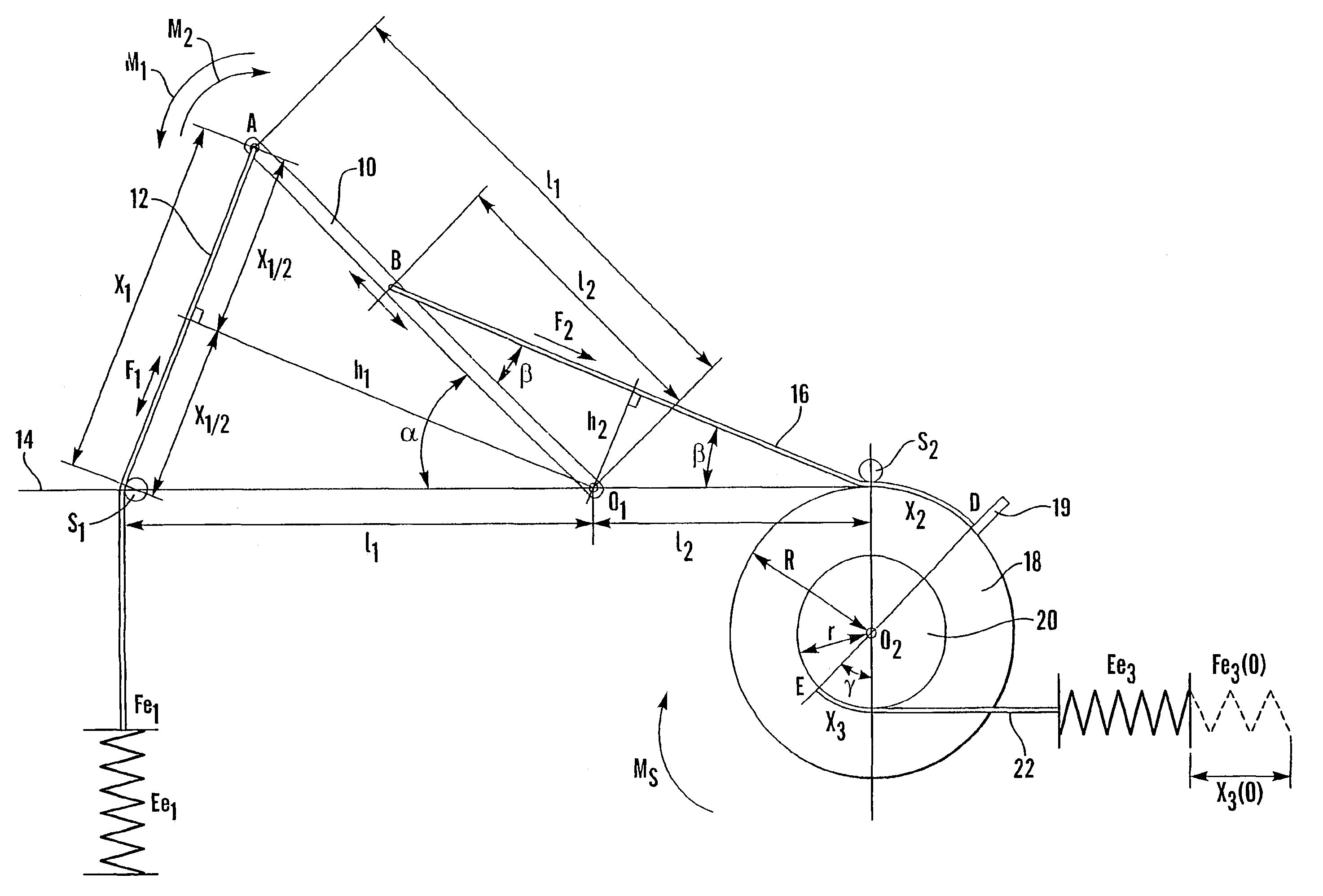
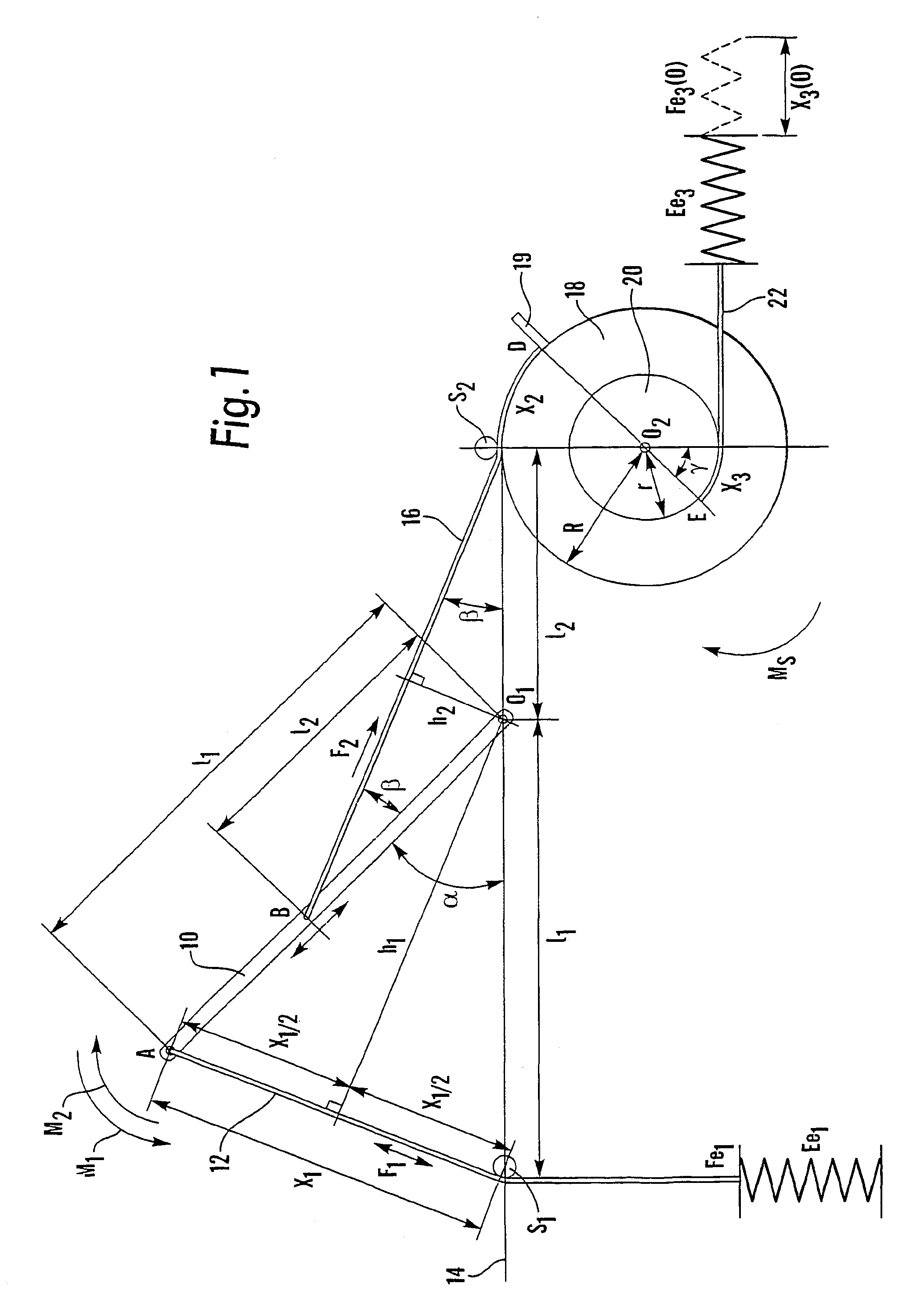
[0025]The principle according to the present invention will be described in conjunction with the device shown in FIG. 1. It comprises an arm 10 with a length l1 rotatably attached with one end to a shaft O1. The area of rotation α is within a range 0≦α≦π radians. A flexible but inelastic band 12, hereafter named first band, is attached to the free end A of the arm. It is to be understood that the wording “flexible but inelastic” is meant to define a band or wire that is substantially free of elasticity in the longitudinal direction of the band but can be bent in the transversal direction. The band runs downwards over a pulley wheel S1, which pulley wheel is arranged on a horizontal plane 14 in FIG. 1, which plane intersects the axis of rotation of the arm 10 and with the same distance between the pulley wheel and the axis of rotation as the length of the arm 11=A O1=S1O1. The first band is attached to an elastic element Ee1.

[0026]When turning the arm 10 clock-wise an angle α, the po...


PUM


Abstract

The present invention relates to a device for obtaining a predetermined linear force, including a first elastic force means (Ee 1, 56) and a force output means (16, 76) in the form of a non-elastic, flexible elongated member. The invention is characterised by a force transformation means (10, 12, 72) arranged between said first elastic force means and the force output means, such that a pulling of the force output means creates a tension in said first elastic force means, and wherein the force transformation means is arranged and designed such that the pulling force required on the force output means decreases with the distance (X2) the force output means is pulled.

Description

TECHNICAL FIELD[0001]The present invention relates to a device for obtaining predetermined linear forces, and in particular to a device where the force obtained is substantially constant. These forces are primarily intended for training of the skeleton muscles, but due to its exceptional properties they can be used in various medical, technical and other applications where its features are beneficial.BACKGROUND OF THE INVENTION[0002]Most of the training equipment present on the market today are designed according to a few construction concepts: devices based on the movement of weights, devices comprising springs and other elastic elements, devices based on friction, actuators like clutches, brakes, fluid valves, (pneumatic, hydraulic), etc. and motor-driven devices.[0003]In order to gain an insight into a training progression and to optimise the training result, it is extremely important to control the relevant movement parameters for muscles such as: load force, contraction speed, ...

Claims


Application Information

Patent Timeline
Patent Type & Authority Patents(United States)
IPC IPC(8): A63B21/00A63B21/002A63B21/02A63B21/04A63B21/055
CPCA63B21/00072A63B21/002A63B21/023A63B21/159A63B21/154A63B21/0428A63B21/04
Inventor PLAVSIC, VOJIN
Owner PLAVSIC VOJIN
Learn More