
Self-locking power component for orthodontic appliances

a technology of self-locking power and orthodontic appliances, applied in the field of orthodontic appliances and methods, can solve problems such as cumbersome design

Active Publication Date: 2007-01-02
INMAN DONAL P
View PDF4 Cites 10 Cited by
  • Summary
  • Abstract
  • Description
  • Claims
  • Application Information

AI Technical Summary

Problems solved by technology

Such force applying arrangements heretofore available have a number of limitations such as being cumbersome in design, being subject to failure caused by screw thread stripping or slipping and providing limited access to adjustment components due to intra-oral environment.
All of these arrangements have the added disadvantage of requiring adjustment by a clinician thereby necessitating an office visit for each adjustment.

Method used


Image

  • Self-locking power component for orthodontic appliances
  • Self-locking power component for orthodontic appliances
  • Self-locking power component for orthodontic appliances

Examples


Embodiment Construction

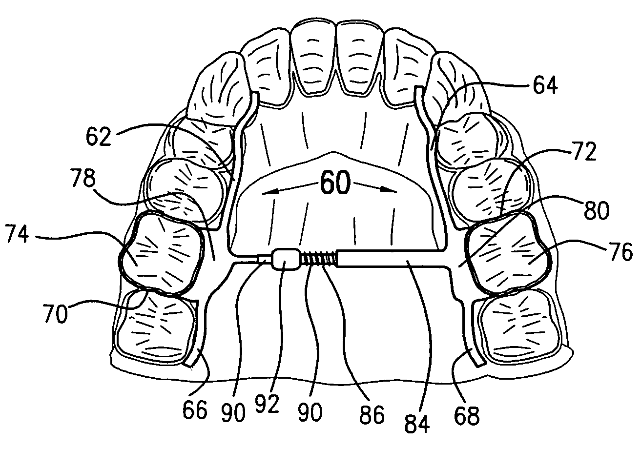
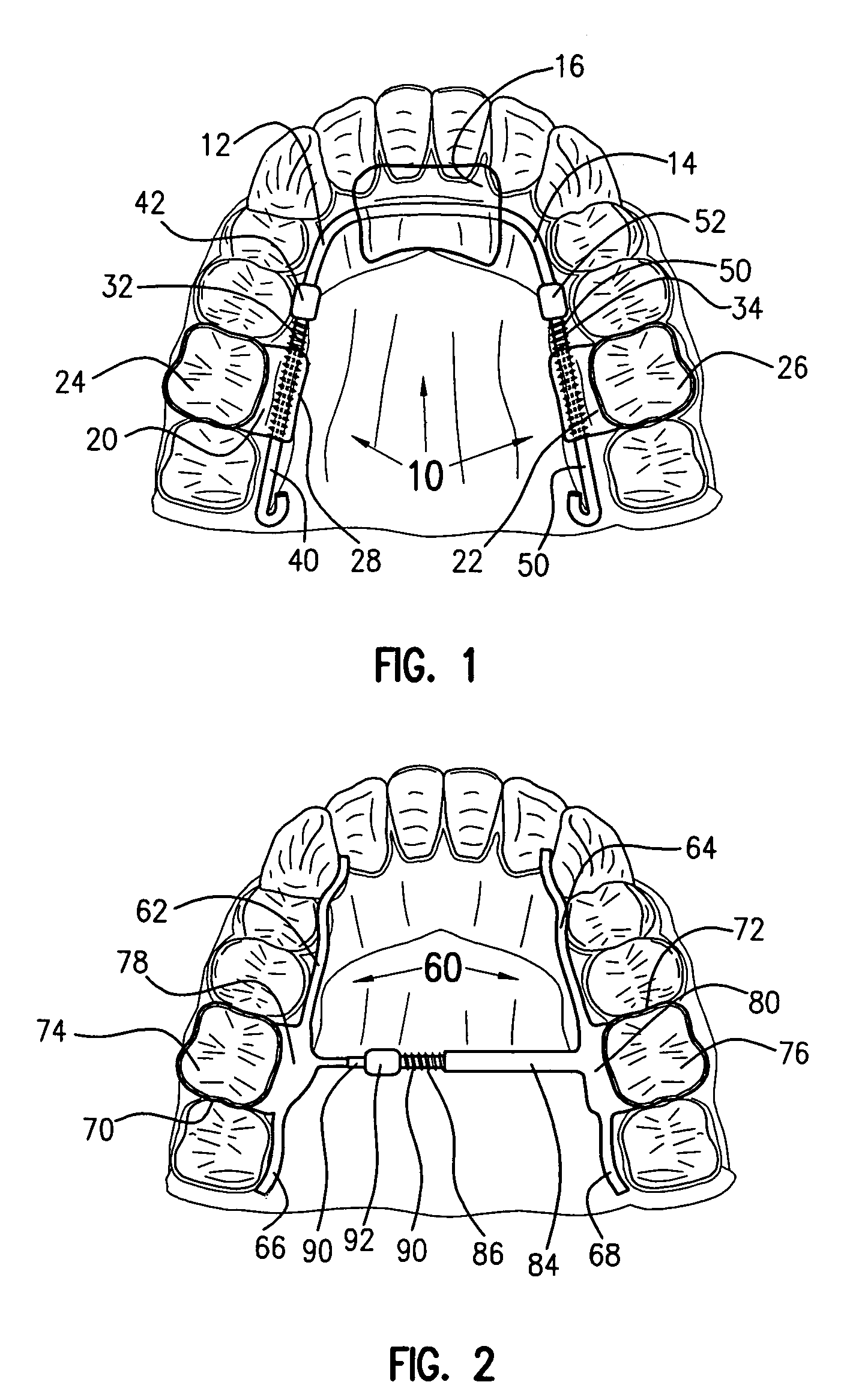
[0027]The force adjusting mechanism of the present invention is readily incorporated in and highly effective in a wide variety of orthodontic appliances, one of such appliances being designated 10 in FIG. 1. Appliance 10 is representative of a number of types of orthodontic appliances which apply force to a patient's teeth in a direction generally longitudinally of the dental arch, i.e. in a direction extending between the front and rear of the dental arch. Appliance 10 includes a first portion which is anchored or supported in the patient's dental arch. Members 12 and 14 of the appliance frame are secured in a plate-like component 16 of plastic or like material which abuts the inner surfaces of the patient's front teeth and the adjacent tissue. Appliance 10 has a second portion including spring means which applies force to one or more of the patient's teeth. A pair of bands 20 and 22 are attached to molar teeth 24 and 26, respectively, in a known manner. Band 20 has an integral bos...


PUM


Abstract

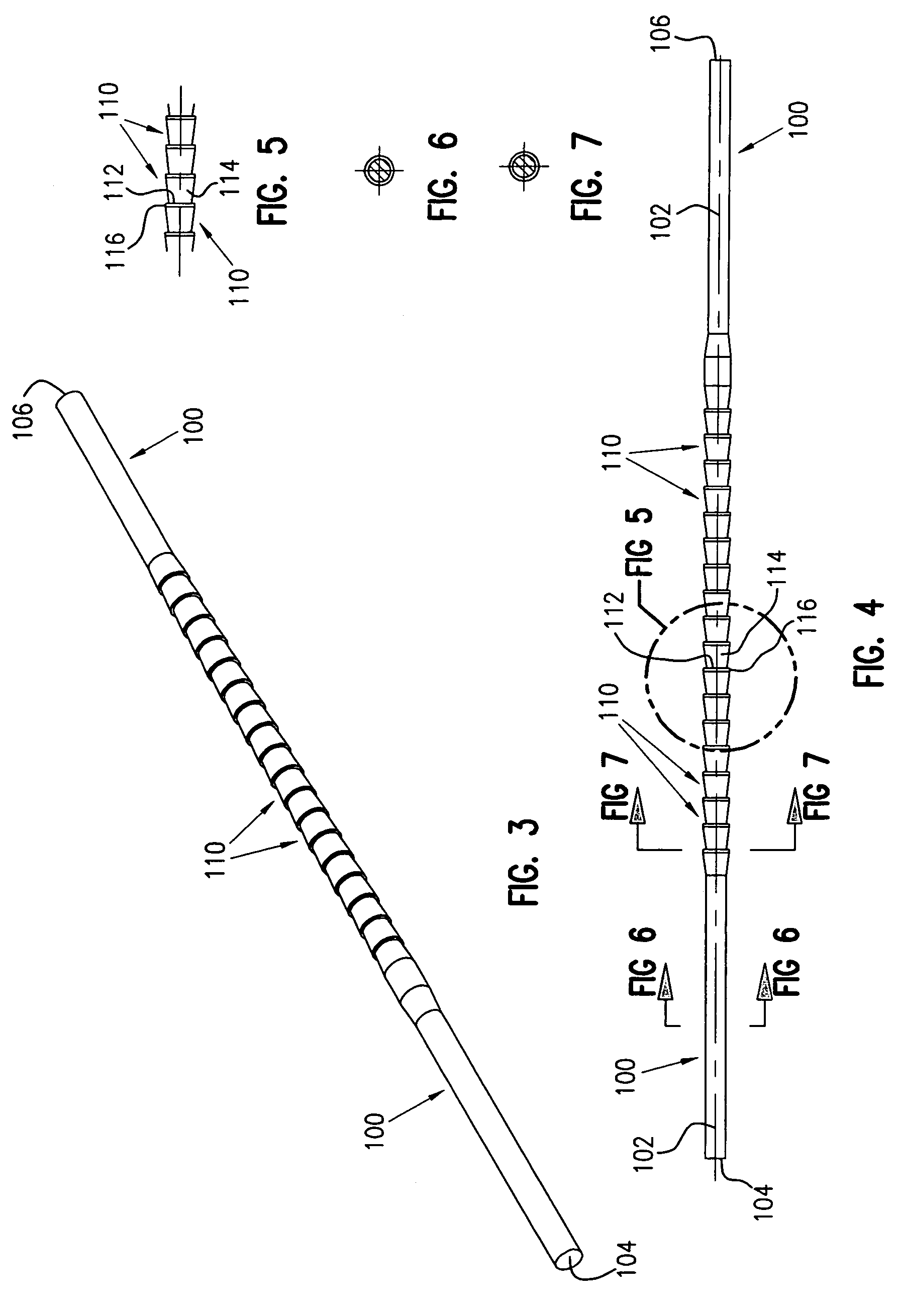
A force adjusting mechanism for an orthodontic appliance wherein the appliance functions to move teeth and / or to expand the dental arch. The mechanism includes a shaft operatively coupled at opposite ends between a first portion of the appliance which is anchored in the patient's dental arch and a second portion of the appliance which applies force to one or more of the patient's teeth. A lock is slidable along the shaft to compress a spring between the lock and the second portion of the appliance. Co-operating structures on the shaft and on the lock provide a unidirectional ratchet movement of the lock along the shaft. Thus, the lock may be advanced one step at a time in one direction only, preferably manually using an implement for engaging the lock, to compress the spring to apply force to one or more of the patient's teeth. Advantageously, this may be done by the patient or a parent or guardian without the need for an office visit to a clinician. The cooperating structures can include a series of successive detent formations along the shaft and a component on the lock moveable into and out of the detent formations thereby avoiding thread stripping or slippage.

Description

CROSS-REFERENCE TO A RELATED APPLICATION[0001]Applicant claims priority based on U.S. provisional patent application No. 60 / 462,839 filed Apr. 16, 2003 and entitled “S.L.P.M Self-Locking Power Module”, the disclosure of which is hereby incorporated by reference.BACKGROUND OF THE INVENTION[0002]This invention relates to the art of orthodontic appliances and methods, and more particularly to a new and improved force adjusting mechanism and method of operating the same for use in orthodontic appliances.[0003]Various orthodontic appliances have mechanisms or components which provide force for moving teeth and / or expanding the dental arches. During the course of treatment, as the teeth are moved toward the desired position / location, it is necessary periodically to adjust the mechanisms / components so that the required amount of force is continued to be applied to the teeth. Such force applying arrangements heretofore available have a number of limitations such as being cumbersome in desig...

Claims


Application Information

Patent Timeline
Patent Type & Authority Patents(United States)
IPC IPC(8): A61C3/00A61C7/00A61C7/02A61C7/10
CPCA61C7/00A61C7/10A61C7/02
Inventor INMAN, DONAL P.
Owner INMAN DONAL P
Learn More