
Electrical machine with double-sided rotor

a technology of electric machines and rotors, which is applied in the direction of electric generator control, machines/engines, mechanical equipment, etc., can solve the problems of increasing noise and cost of wind turbines, reducing the reliability of wind turbines, and large diameters of direct drive generators, so as to reduce diameters, increase power ratings, and reduce costs

Inactive Publication Date: 2006-12-26
GENERAL ELECTRIC CO
View PDF57 Cites 136 Cited by
  • Summary
  • Abstract
  • Description
  • Claims
  • Application Information

AI Technical Summary

Benefits of technology

"The present invention provides a wind turbine with a generator that has at least two concentric air gaps. The generator includes a double-sided rotor and a stator with inner and outer stator cores. The double-sided rotor is concentrically disposed between the inner and outer stator cores. This design improves the performance and efficiency of the wind turbine. Additionally, the invention also provides a ship propulsion motor with a similar design."

Problems solved by technology

The drawback of a geared drive is that it reduces the reliability of the wind turbine and increases the noise and cost of the wind turbine.
The large diameters of direct drive generators present formidable transportation and assembly challenges, both at the factories and at the wind turbine installation site.
Increasing the diameter is preferred from a purely generator electromagnetic perspective, but is not attractive from the transportation, frame, and assembly perspective, especially for land-based turbines.
Increasing the axial length of the generators, while maintaining the diameter to be less than approximately 4.1–4.3 meters, alleviates the land-based transportation issue, but results in complex and costly frame structures with long axial extents.

Method used


Image

  • Electrical machine with double-sided rotor
  • Electrical machine with double-sided rotor
  • Electrical machine with double-sided rotor

Examples


Embodiment Construction

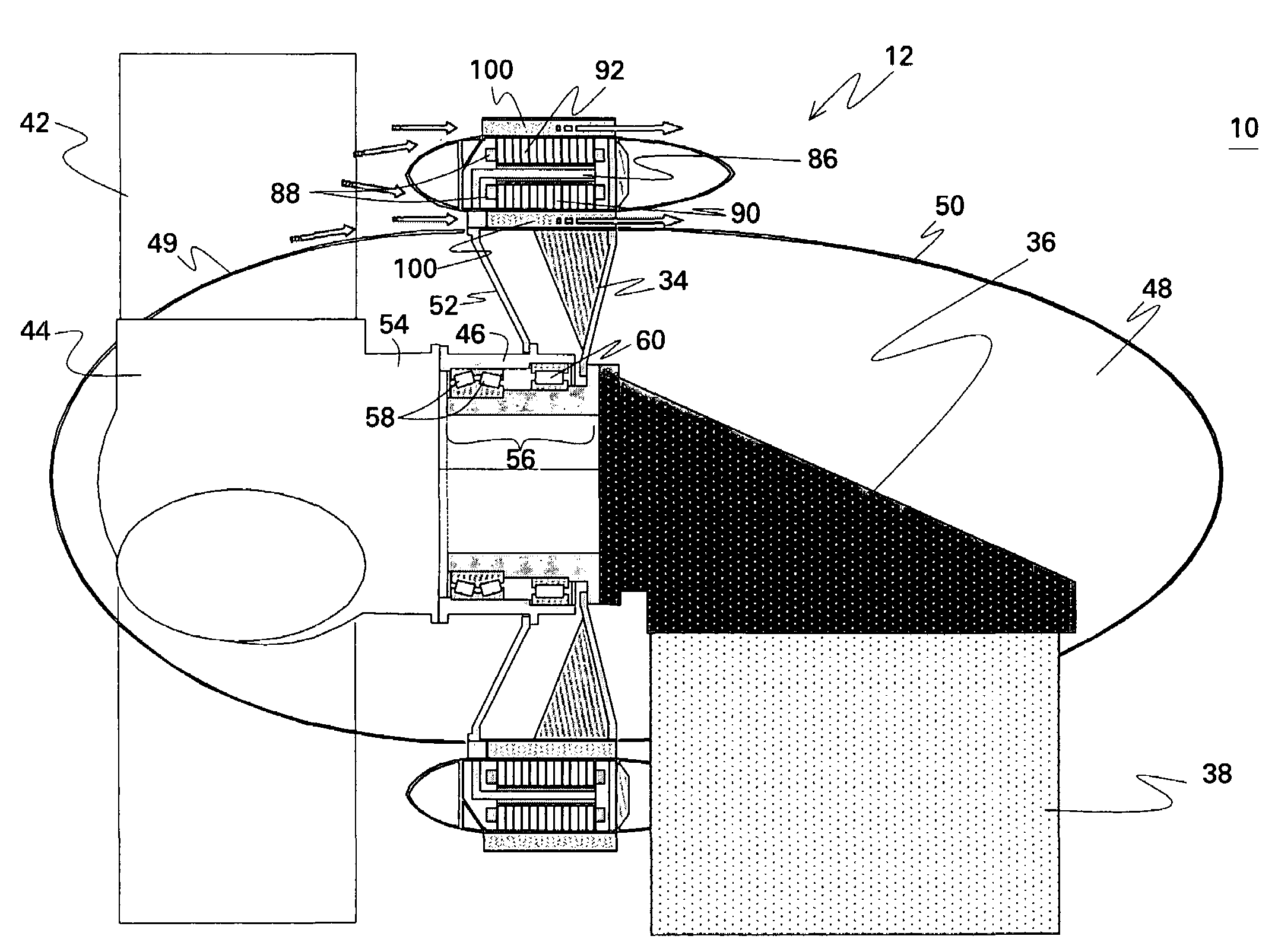
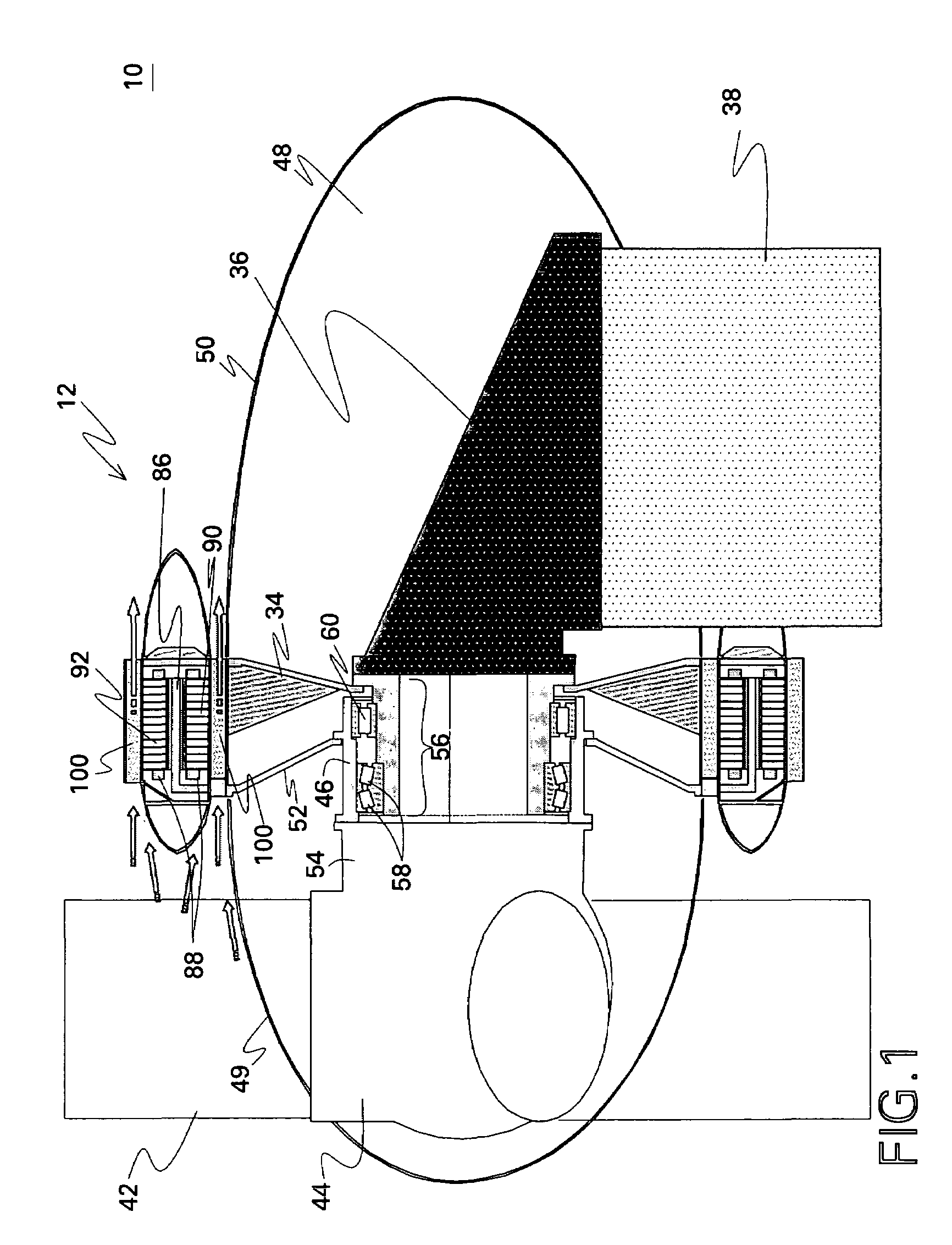
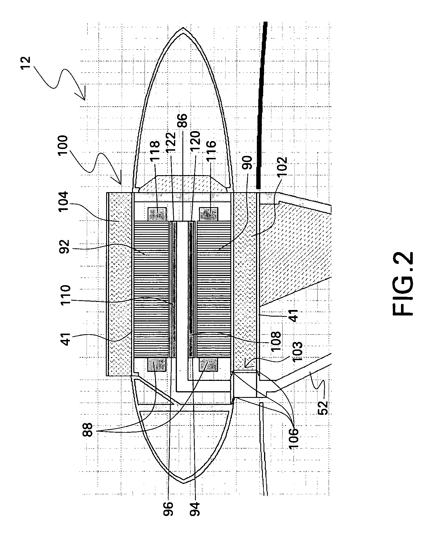
[0019]The present invention includes different embodiments for double-sided generators and motors that are particularly useful for direct-drive wind turbines and ship propulsion units. Additionally these embodiments may be beneficial for some geared electrical machines. The different configurations described herein below are based upon a double-sided, radial-flux, synchronous electrical machines. Although permanent magnet (PM) machines are described and shown for purposes of illustration, other electrical machines such as wound field machines can alternatively be used. These configurations contribute towards achieving cost-effective wind turbines of increased power ratings (>2.0 MW) and are especially advantageous for land-based applications where the outside diameter may be constrained by transportation limitations.

[0020]Turning now to the figures, FIG. 1 is a diagrammatic representation of a sectional view of a wind turbine 10 with an exemplary embodiment of a direct-drive double-...


PUM


Abstract

Machines useful for wind turbine and ship propulsion purposes include a double-sided generator or motor with two concentric air gaps. In one embodiment, the machine includes a double-sided rotor with an inner rotor side and an outer rotor side; and a stator with an inner stator core and an outer stator core, wherein the double-sided rotor is concentrically disposed between the inner stator core and the outer stator core.

Description

BACKGROUND OF THE INVENTION[0001]The present invention relates generally to electrical machines and more specifically to wind turbine generators and ship propulsion motors.[0002]Wind is usually considered to be a form of solar energy. Wind is caused by the uneven heating of the atmosphere by the sun, the irregularities of the earth's surface, and rotation of the earth, and wind flow patterns are modified by the earth's terrain, bodies of water, and vegetation. The terms wind energy or wind power describe the process by which the wind is used to generate mechanical power or electricity.[0003]Typically, wind turbines are used to convert the kinetic energy in the wind into mechanical power. This mechanical power may be used for specific tasks (such as grinding grain or pumping water) or a generator may convert this mechanical power into electricity. A wind turbine usually includes an aerodynamic mechanism for converting the movement of air into a mechanical motion which is then convert...

Claims


Application Information

Patent Timeline
Patent Type & Authority Patents(United States)
IPC IPC(8): F03D9/00
CPCF03D9/00H02K5/20H02K9/20H02K21/14H02K21/22H02K7/1838F05B2220/70642F05B2220/7066F05B2220/7068H02K16/04Y02E10/725Y02E10/728F03D9/25F03D13/20F03D80/60Y02E10/72H02K9/225H02K5/207H02K5/203
Inventor JANSEN, PATRICK LEELYONS, JAMES PATRICKCARL, JR., RALPH JAMESQU, RONGHAIFOGARTY, JAMES MICHAEL
Owner GENERAL ELECTRIC CO
Learn More