
Front mounted zero turn radius walk behind sprayer

a zero-turn radius, front mounted technology, applied in the direction of applications, roads, roads, etc., can solve the problems of high deposition rate, high deposition rate, and propagation of unwanted turf invasion, so as to prevent unwanted treatment of the border area, accurate traverse, and accurate traverse

Inactive Publication Date: 2006-12-26
JOHNSON WILLIAM D
View PDF8 Cites 28 Cited by
  • Summary
  • Abstract
  • Description
  • Claims
  • Application Information

AI Technical Summary

Benefits of technology

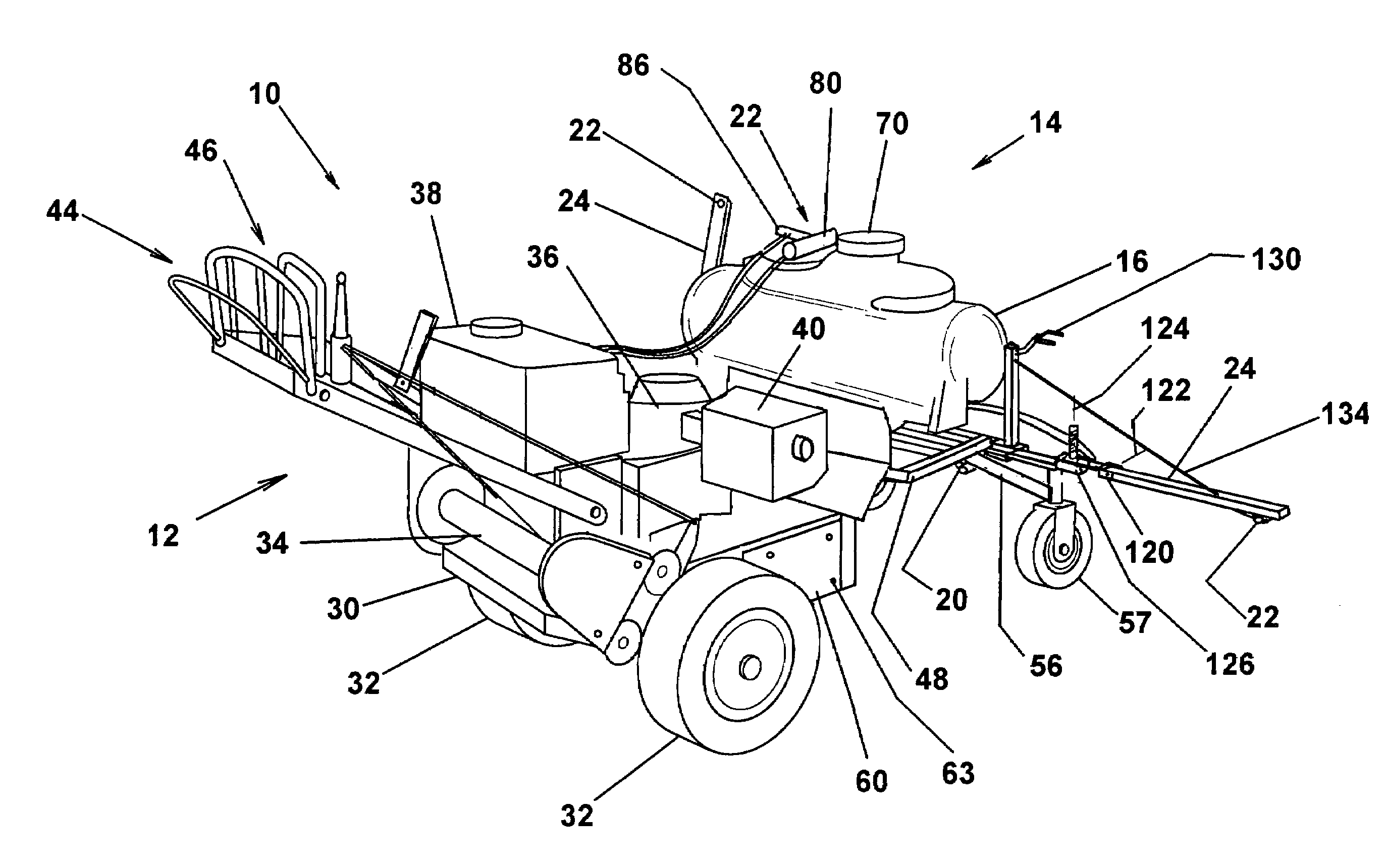
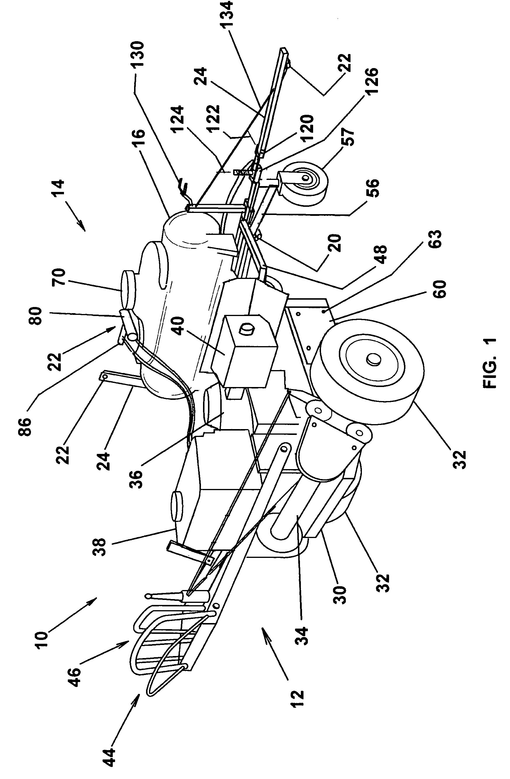
[0008]The present invention comprises a walk behind zero turn radius (ZTR) drive unit and a front spray frame carrying a plurality of transversely spaced, clearly observable spray nozzles. The drive unit permits accurate and high productivity traverse of the application area with the ability to steer around obstacles and accurately traverse an irregular edging pattern. The spray frame includes a pair of folding spray arms having a first sect of dispensing nozzles. Another set of nozzles is positioned at the outer sides of the frame. All the nozzles are within the forward lateral view of the operator permitting ready steering of the drive unit around the borders of the application area. The nozzles are supplied with liquid from a frame mounted tank by an electric pump powered by the drive unit. The spray nozzles are controlled by an operator valve positioned adjacent the drive unit control, thereby allowing the operator to control the application during travel. For narrower application paths the boom arms may be raised and the boom nozzles inactivated by the control valve. The sprayer is also provided with an edging curtain that is removably mounted at the sides of the frame. The curtain provides a lateral spray barrier and drip edge that, in combination the ZTR drive, provides close delineation between adjacent areas to prevent unwanted treatment of a border area.
[0009]Accordingly, it is an object of the present invention to provide a motorized lawn treatment sprayer that is highly maneuverable in establishing a desired liquid spray pattern.
[0010]Another object of the invention is to provide a walk behind lawn treatment sprayer wherein the sprayer nozzles are operative in the front of the operator for clear visibility in establishing a delineated spray pattern with an adjacent area.
[0011]A further object is to provide a liquid treatment sprayer using a walk behind zero radius turn drive unit to provide high maneuverability and front mounted transverse spray nozzles that can be directly operator observed for accuracy in application.
[0012]A further object is to provide a liquid lawn treatment sprayer having a lateral drip barrier that prevents unwanted application to on adjacent areas.

Problems solved by technology

One of the difficulties has been accurately applying such additives at high depositions rates in areas requiring clear delineation of growth.
If the fertilized is applied in the mulched areas, unwanted turf invasion is promoted.
Application beyond the intended boundary can promote invasion of an unwanted species and a loss of the desired pattern.
While hand held spraying devices may be relatively accurately controlled, the application rate is low and labor costs are high, limiting the attractiveness in larger areas.
Accordingly motorized spraying units are available for spraying larger areas, but have not overcome the problems of accurately defining the spray pattern at borders of contrasting landscape.
As with the above approaches, the operator is not able to see directly the spray pattern to avoid application in adjacent areas requiring different treatment protocols.
Also the surrounding housings preclude direct observation of the application pattern and are limited in the ability to accurately maneuver around defined areas and obstacles.

Method used


Image

  • Front mounted zero turn radius walk behind sprayer
  • Front mounted zero turn radius walk behind sprayer
  • Front mounted zero turn radius walk behind sprayer

Examples


Embodiment Construction

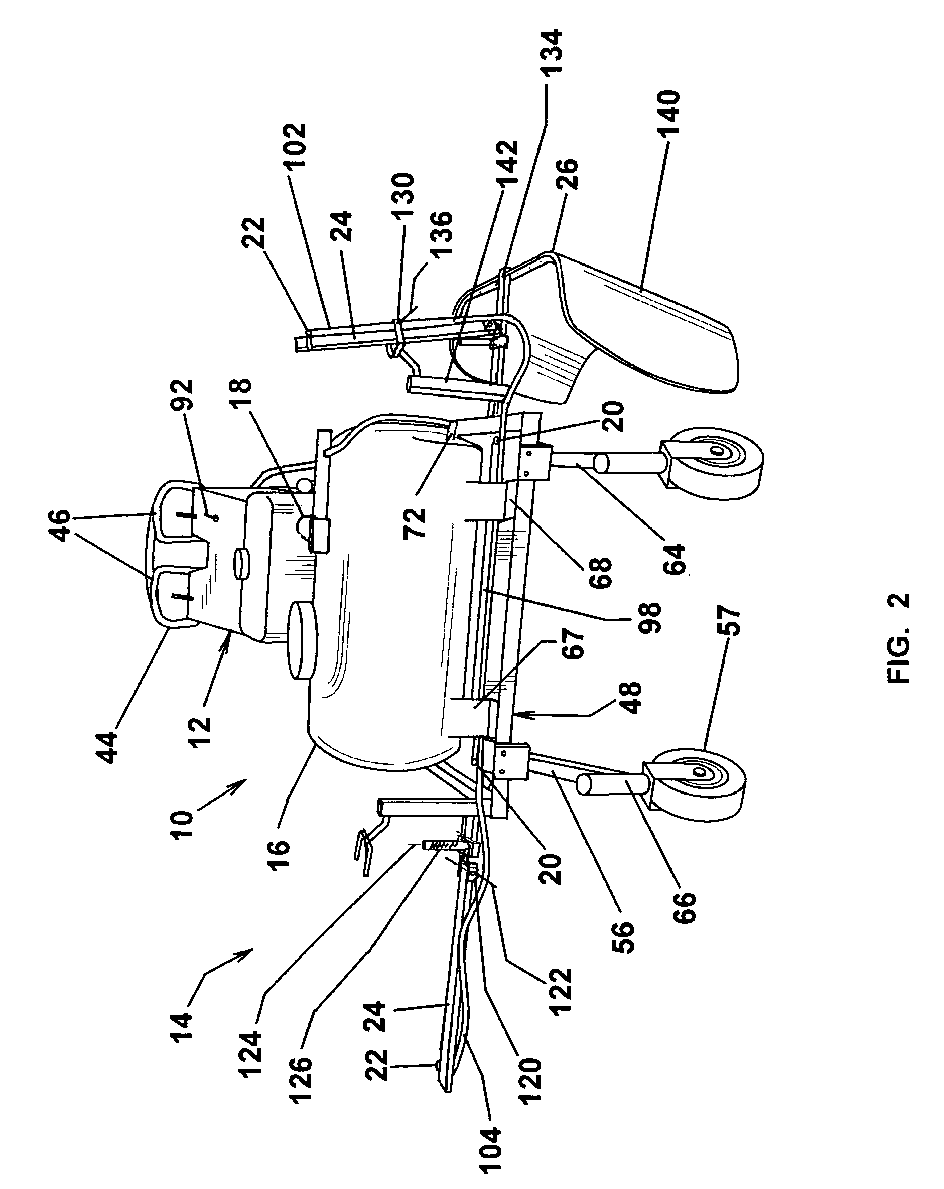
[0021]Referring to the drawings, FIGS. 1 and 3 illustrate a front mounted zero turn radius (ZTR) walk behind sprayer 10 comprising a drive unit 12 and a sprayer assembly 14 coupled thereto. The sprayer assembly 14 includes a tank 16 for carrying turf treatment liquids, such as fertilizers and pesticides. The liquids are delivered from the tank 16 by liquid dispensing system 18 to distribution lines including a first set nozzles 20 on the sprayer assembly and second set of nozzles 22 mounted on transverse folding sprayer arms 24. The nozzles 20,22 spray liquids downwardly and rearwardly. As shown in FIG. 2, with one of the folding arms 24 in the raised position, the sprayer assembly 14 may include a releasably attached edging curtain assembly 26 for accurate delineation of spray patterns around non-turf areas such as trees or shrubbery, or between different grass species.

[0022]The drive unit 12 is a suitable commercially available zero turn radius gasoline powered assembly of the typ...


PUM


Abstract

The present invention comprises a walk behind zero turn radius drive unit and a front spray frame carrying a plurality of transversely spaced, clearly observable spray nozzles. The drive unit permits accurate and high productivity traverse of the application area with the ability to steer around obstacles and accurately traverse an irregular edging pattern. The spray frame includes a pair of folding spray arms, each of which carried dispensing nozzles. Another set of nozzles is positioned at the sides of the frame. All the nozzles are within the forward lateral view of the operator permitting ready steering of the drive unit around the borders of the application area. The nozzles are supplied with liquid from a frame mounted tank by an electric pump powered by the drive unit. The spray nozzles are controlled by an operator valve positioned adjacent the drive unit control, thereby allowing operator to control the application during travel. For narrower application paths the boom arms may be raised and the boom nozzles inactivated by the control valve. The sprayer is also provided with an edging curtain that is removably mounted at the sides of the frame. The curtain provides a lateral spray barrier and drip edge that, in combination the ZTR drive, provides close delineation between adjacent areas to prevent unwanted treatment of a border area.

Description

FIELD OF THE INVENTION[0001]The present invention relates to motorized apparatus for spraying liquid additives and, in particular, to a front mounted spray assembly on a walk behind zero turn radius chassis that provides rapid and accurate spray patterns of liquid additives.BACKGROUND OF THE INVENTION[0002]Many motorized approaches have been taken for applying additives such as nutrients and chemical modifiers, to soil for promoting growth and controlling foliage control to lawns and turf. One of the difficulties has been accurately applying such additives at high depositions rates in areas requiring clear delineation of growth. For instance, shrubbery and trees preferably have desired borders between the lawn and the surrounding mulch. If the fertilized is applied in the mulched areas, unwanted turf invasion is promoted. Similarly, in recreational areas, such as golf courses, different grasses are used for greens, fairways, approaches, and roughs. Each requires a different treatmen...

Claims


Application Information

Patent Timeline
Patent Type & Authority Patents(United States)
IPC IPC(8): B05B1/20
CPCA01M7/0039A01M7/0064
Inventor JOHNSON, WILLIAM D.
Owner JOHNSON WILLIAM D
Learn More