
Brake flush accelerator

a technology of brake fluid and accelerator, which is applied in the field of brake system system and method of flushing, can solve the problems of difficult removal of brake fluid contamination, excessive time required to properly flush the system, and limited flow of brake fluid through the system, so as to reduce the flush time, increase the fluid volume and pressure, and accurately control the piston stroke

Active Publication Date: 2006-12-26
PHOENIX SYST
View PDF5 Cites 11 Cited by
  • Summary
  • Abstract
  • Description
  • Claims
  • Application Information

AI Technical Summary

Benefits of technology

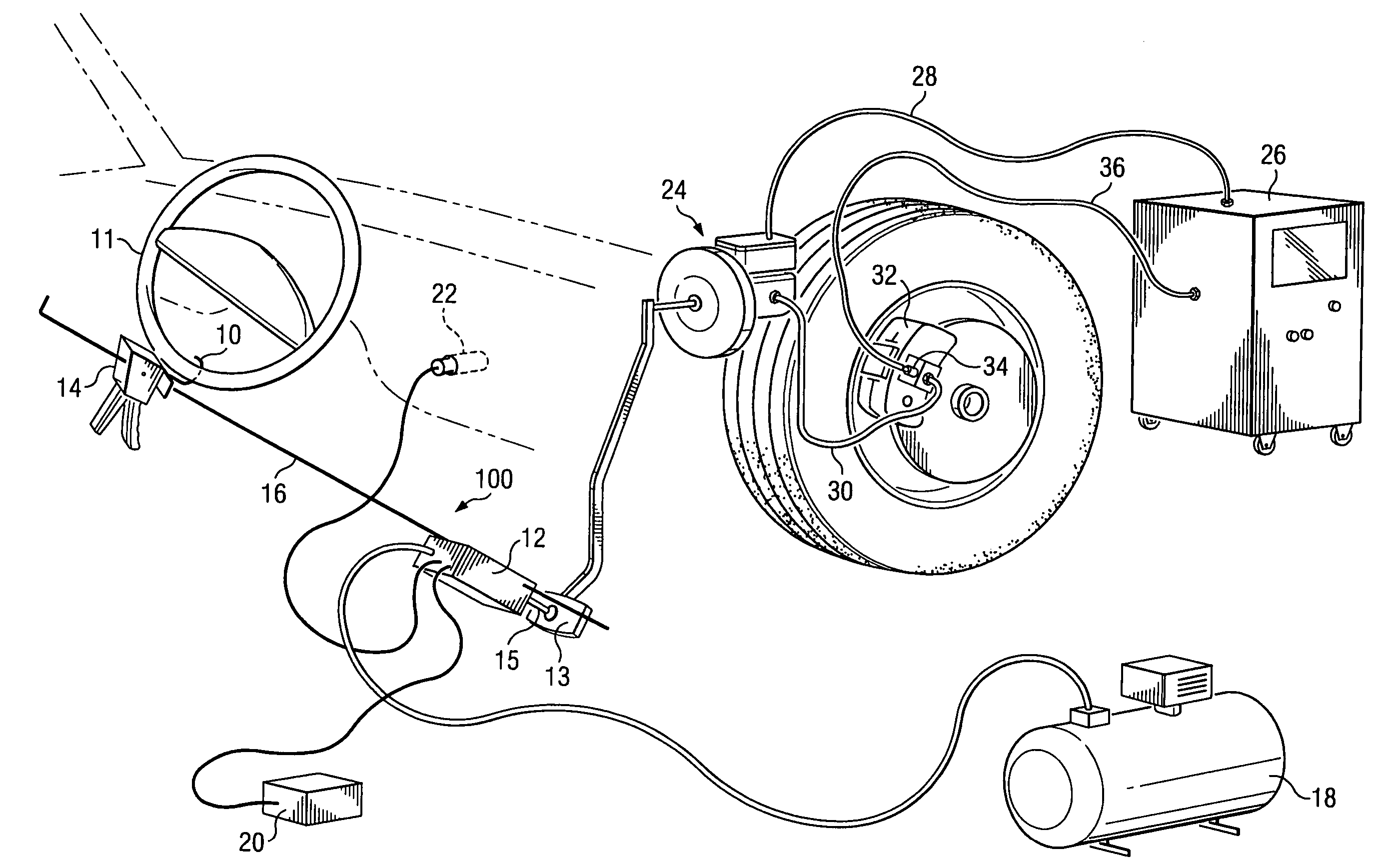
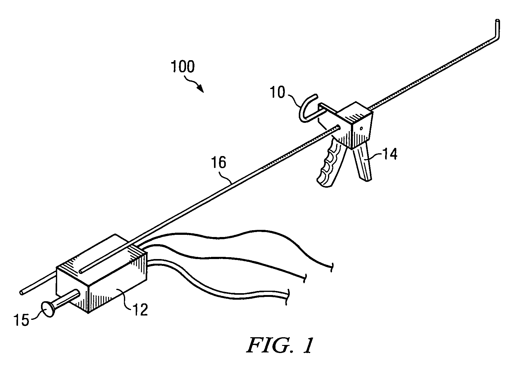
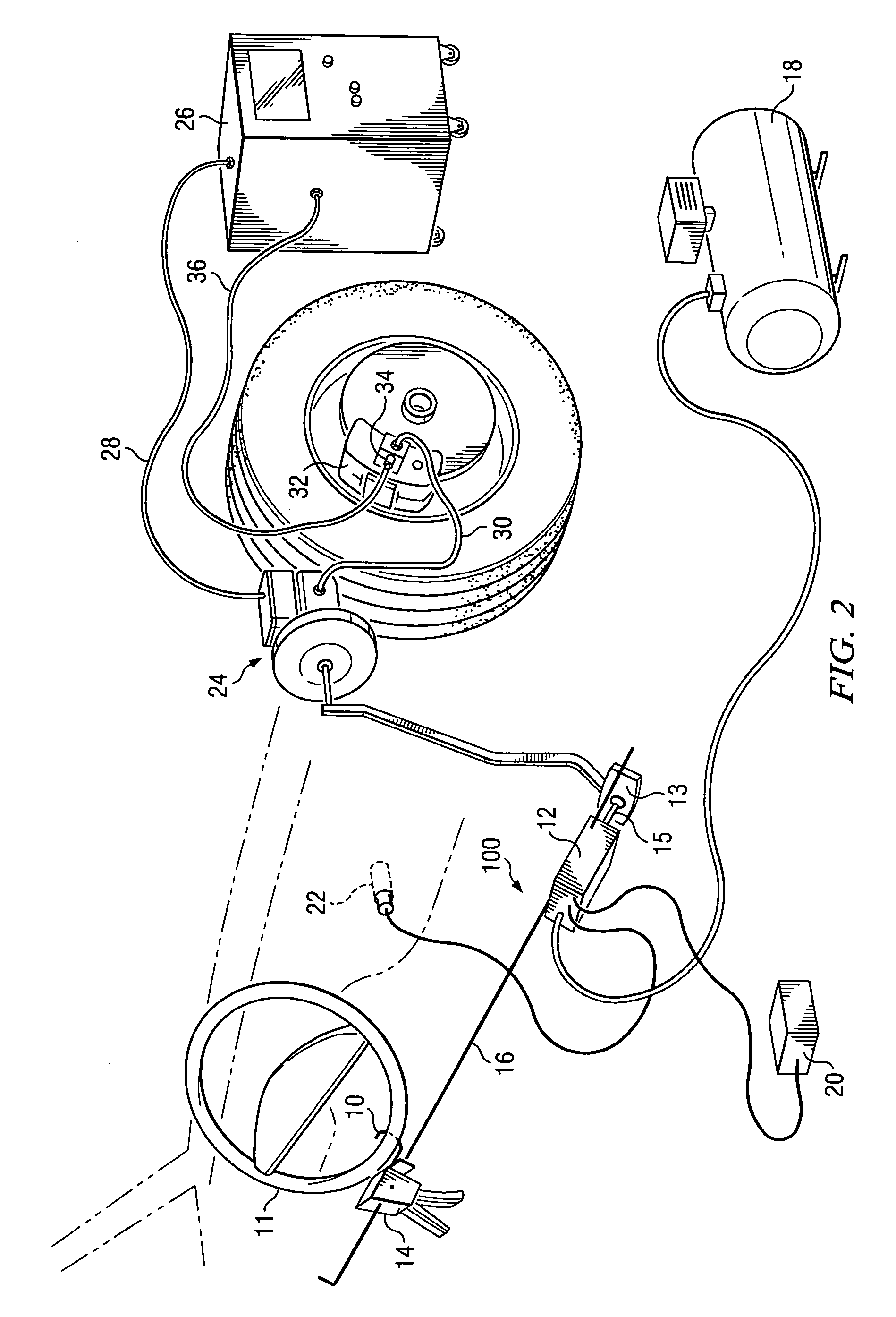
"The patent describes a new brake flush machine that uses a Brake Flush Accelerator (BFA) to flush brakes properly. The BFA selectively depresses the brake pedal while the brakes are being flushed, reducing the time needed for the flush and increasing the amount of fluid pressure. The BFA also allows the low / no pressure area of the master cylinder to be flushed. The BFA can be used as a self-contained module or in conjunction with existing brake flush machines. It is powered by an air compressor or a car tire, and can be attached to vehicle battery power or directly powered by the brake flush machine. The BFA accurately controls the piston stroke and rate of pedal depression and release, ensuring a proper brake flush."

Problems solved by technology

As a result, the brake fluid flow through the system is limited and takes excessive time to properly flush the system.
Most reservoirs are a composite or plastic material and cannot be exposed to pressures above 20 pounds-per-square-inch (PSI) without deforming the shape of the reservoir, causing leakage.
The low pressure also makes removing brake fluid contamination more difficult.
This means that one part of the brake system may experience minimal fluid flow, which will not provide a proper flush.
The downside is that the flush time is lengthened because the flow is isolated to a part of the system and not all the wheels at the same time.
This leaves an area of old fluid that can contaminate the new brake fluid after the flush has been performed.
This is not an indication of a problem with the test strip; rather, it shows that the low / no pressure area was not cleaned during the flush process and the old fluid contaminated the rest of the system.
An isolated brake flush machine could take as long as 30 minutes to properly introduce ½ gallons of brake fluid through the system, while current all-wheel flush machines operate for 10–12 minutes and waste the unused fluid.
Each brake flush machine has severe design flaws; for example, the time to perform service or the quality of the service performed.
The problem with current brake flush machine technology is that it cannot move fluid through the system with enough force to remove contamination.

Method used


Image

  • Brake flush accelerator
  • Brake flush accelerator
  • Brake flush accelerator

Examples


Embodiment Construction

[0018]The Brake Flush Accelerator Module can be used in conjunction with existing brake flush machines. The invention eliminates the problems with current flush technology and can be used to significantly improve the brake system flush for most types of brake flushing machines.

[0019]The Brake Flush Accelerator Module (BFA) automatically depresses the brake pedal while the master cylinder reservoir is under pressure from the brake flush machine. This accomplishes two main functions. First, the BFA can force fluid through the system at a very rapid rate. Testing has shown that the BFA can pump ½ gallons of brake fluid through the brake system as much as five times faster than standard brake flush machines. The BFA also provides a much more thorough flush as internal hydraulic pressure from the master cylinder can be used to exert much more force to remove contaminates from the system.

[0020]Second, the BFA exposes the low / no pressure area of the master cylinder to fluid flow from the p...


PUM

PropertyMeasurementUnit
pressureaaaaaaaaaa
lengthaaaaaaaaaa
pressuresaaaaaaaaaa

Abstract

A Brake Flush Accelerator (BFA) selectively depresses a brake pedal while the master cylinder reservoir is under pressure from a brake flush machine, forcing fluid through the system at a very rapid rate. The BFA also provides a thorough flush as internal hydraulic pressure from the master cylinder can be used to exert force to remove contaminates from the brake system. The BFA exposes the low / no pressure area of the master cylinder to fluid flow from the pressurized master cylinder. When the brake pedal is depressed, a port in the master cylinder is opened which exposes the low / no pressure area of the master cylinder to fluid flow from the pressurized master cylinder reservoir. The BFA receives its pneumatic power from an air compressor or is easily adapted to a car tire. The BFA can be powered directly from the brake flush machine or attached to a vehicle's battery.

Description

RELATED APPLICATIONS[0001]This application is a continuation-in-part of copending U.S. application Ser. No. 10 / 981,060 entitled “Brake Flush Accelerator” filed Nov. 4, 2004. Additionally, this application claims priority to U.S. provisional Application Ser. No. 60 / 517,296, filed Nov. 4, 2003, entitled “Brake Flush Accelerator.”BACKGROUND OF THE INVENTION[0002]1. Field of the Invention[0003]The present invention relates in general to automotive systems and, in particular, to a system and method of flushing a brake system.[0004]2. Description of the Related Art[0005]Anti-lock brake system (ABS) design utilizes multiple hydraulic passage ways and valving that restrict fluid movement. As a result, the brake fluid flow through the system is limited and takes excessive time to properly flush the system. The pressure that can be exerted on the system is limited by the master cylinder reservoir adapter. The adapter connects the pressurized fluid from the brake flush machine to the master cy...

Claims


Application Information

Patent Timeline
Patent Type & Authority Patents(United States)
IPC IPC(8): B65B1/04B60T17/22G05G1/48
CPCB60T17/222B60T17/223
Inventor PETTY, JON A.
Owner PHOENIX SYST
Learn More