
Apparatus and method of driving display device

a display device and apparatus technology, applied in the field of apparatus and a method of driving a display device, can solve the problem of relatively low light efficiency of three color lcd

Active Publication Date: 2006-12-19
SAMSUNG DISPLAY CO LTD
View PDF3 Cites 37 Cited by
  • Summary
  • Abstract
  • Description
  • Claims
  • Application Information

AI Technical Summary

Benefits of technology

The patent describes an apparatus and method for driving a display device with four color pixels. The apparatus includes an input unit for receiving three color image signals and converting them into four color image signals. The method involves comparing the grays of the input image signals to determine a maximum, middle, and minimum input gray, and assigning an order index to the signals. The method then gamma-converts the maximum, middle, and minimum input grays to generate the four color image signals. The four color image signals have a plurality of grays representing luminance and luminance difference between higher and lower grays, with the order index applying an order of the grays to the signals. The technical effect of this patent is to provide a more accurate and precise method for driving a display device with four color pixels.

Problems solved by technology

However, such a three color LCD has relatively low light efficiency since the red, green, and blue color filters transmits incident light by one thirds.

Method used


Image

  • Apparatus and method of driving display device
  • Apparatus and method of driving display device
  • Apparatus and method of driving display device

Examples


Embodiment Construction

[0036]The present invention now will be described more fully hereinafter with reference to the accompanying drawings, in which embodiments of the invention are shown.

[0037]In the drawings, the thickness of layers and regions are exaggerated for clarity. Like numerals refer to like elements throughout. It will be understood that when an element such as a layer, region or substrate is referred to as being “on” another element, it can be directly on the other element or intervening elements may also be present. In contrast, when an element is referred to as being “directly on” another element, there are no intervening elements present.

[0038]Then, apparatus and methods of driving a display device are described with reference to accompanying drawings.

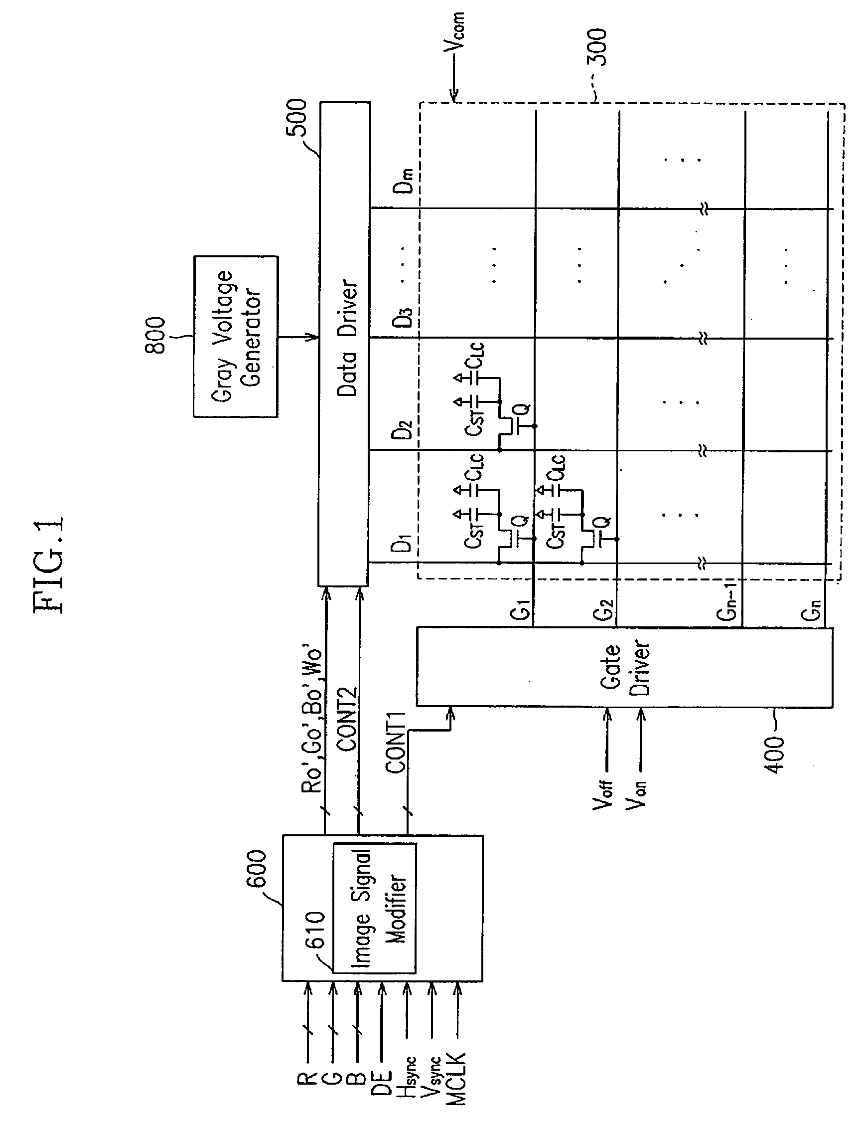
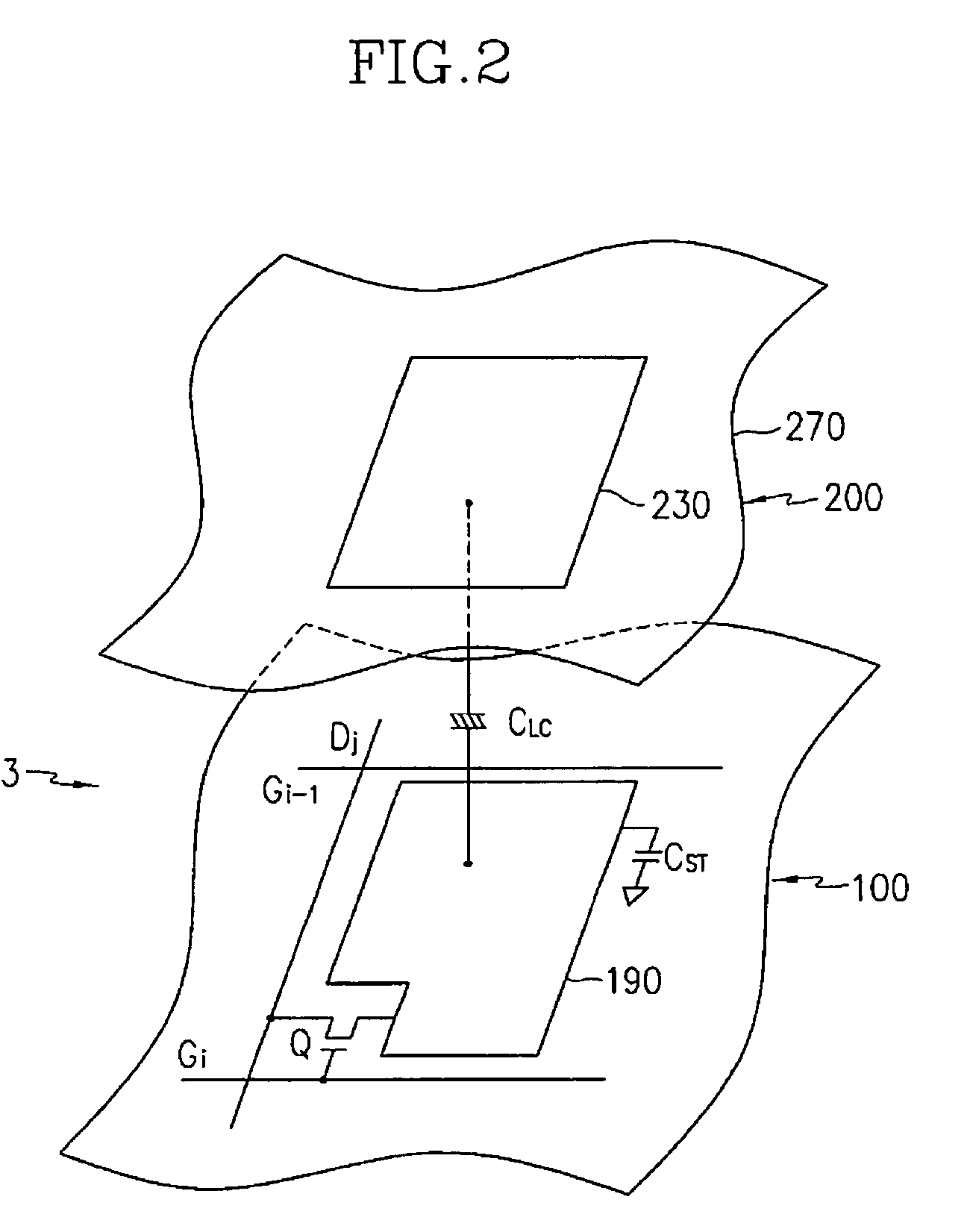
[0039]FIG. 1 is a block diagram of an LCD according to an embodiment of the present invention and FIG. 2 is an equivalent circuit diagram of a pixel of an LCD according to an embodiment of the present invention.

[0040]Referring to FIG. 1, an ...


PUM

PropertyMeasurementUnit
total light transmittanceaaaaaaaaaa
inclination angleaaaaaaaaaa

Abstract

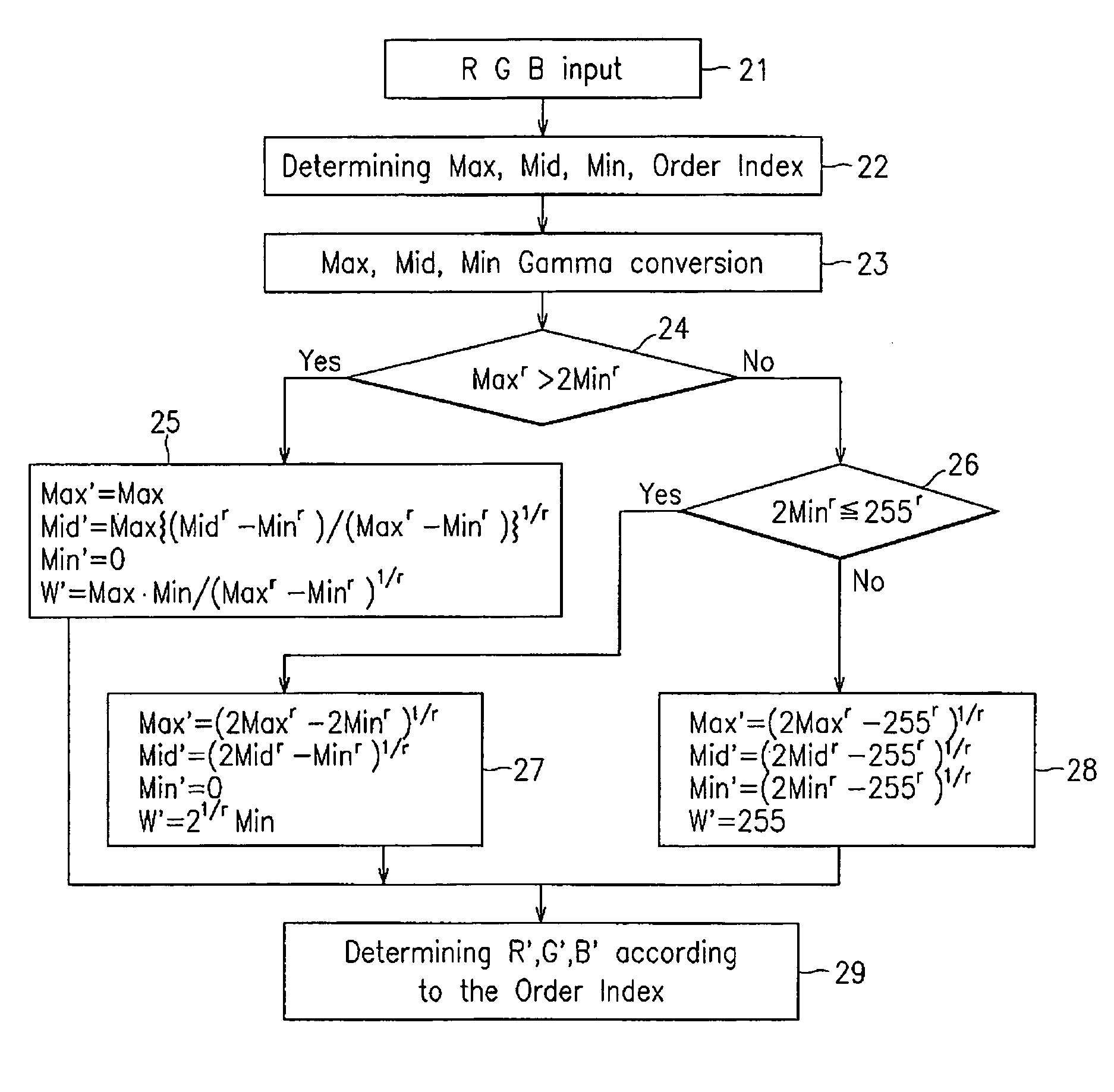
Grays of input image signals in a set of input three-color image signals are compared to determine a maximum input gray (Max), a middle input gray (Mid), and a minimum input gray (Min) among the input image signals and to assign an order index to the signal set. The Max, Mid, and Min are gamma-converted into Γ(Max), Γ(Mid), and Γ(Min), respectively, and a maximum output gray (Max′), a middle output gray (Mid′), a minimum output gray (Min′), and an output white signal (W′) are determined. The four color image signals are generated from the Max′, Mid′, Min′, and W′ based on the order index.

Description

BACKGROUND OF THE INVENTION[0001]1. Field of the Invention[0002]The present invention relates to an apparatus and a method of driving a display device.[0003]2. Description of the Related Art[0004]Display devices include a cathode ray tube (CRT), a plasma display panel (PDP), a liquid crystal display (LCD), an organic electro luminance (EL) display, etc. The display devices are used for various devices such as monitors, television sets, indoor and outdoor signboards, etc., and they are required to have high luminance for the television sets and the signboards. The LCD, which is a non-emissive display, has one of main disadvantages of low luminance.[0005]An LCD includes two panels provided with field-generating electrodes such as pixel electrodes and a common electrode and a liquid crystal (LC) layer with dielectric anisotropy disposed between the panels. The pixel electrodes are arranged in a matrix and connected to switching elements such as thin film transistors (TFTs) such that th...

Claims


Application Information

Patent Timeline
Patent Type & Authority Patents(United States)
IPC IPC(8): G09G3/36G02F1/133G09G3/20G09G5/10
CPCG09G3/3607G09G3/3648G02F2201/52G09G2300/0452G09G2320/0673G09G2340/0428G09G2340/06G09G3/36
Inventor LEE, BAEK-WOON
Owner SAMSUNG DISPLAY CO LTD
Learn More