
Method for measuring GPS air sensitivity and mobile terminal having function of measuring GPS air sensitivity

a technology of gps and air sensitivity, which is applied in the direction of transmission, transmission monitoring, instruments, etc., can solve the problems of inaccurate reporting of the air sensitivity of gps to users and no numerical reference for measuring the air sensitivity of gps

Active Publication Date: 2006-12-19
PANTECH CORP
View PDF19 Cites 0 Cited by
  • Summary
  • Abstract
  • Description
  • Claims
  • Application Information

AI Technical Summary

Benefits of technology

[0005]It is, therefore, an object of the present invention to provide a mobile terminal having a function to measure an air sensitivity of global positioning system GPS by obtaining a pulse density modulation value from an auto gain control AGC amplifier in the mobile terminal, without using additional equipment such as a diagnostic monitor.
[0006]It is another object of the present invention to provide a mobile terminal having a function to measure an air sensitivity of global positioning system GPS and displaying the measured air sensitivity on a display unit in the mobile terminal.
[0005]It is, therefore, an object of the present invention to provide a mobile terminal having a function to measure an air sensitivity of global positioning system GPS by obtaining a pulse density modulation value from an auto gain control AGC amplifier in the mobile terminal, without using additional equipment such as a diagnostic monitor.

Problems solved by technology

However, it also has drawbacks.
At first, there is no numerical reference for measuring the air sensitivity of GPS.
Therefore, the air sensitivity of GPS cannot be accurately reported to users.
Secondly, after debugging the GPS in the mobile terminal, whole annoying procedure of measuring method is performed again such as the user has to carry the mobile terminal having GPS functions and brings it outside for field test.

Method used


Image

  • Method for measuring GPS air sensitivity and mobile terminal having function of measuring GPS air sensitivity
  • Method for measuring GPS air sensitivity and mobile terminal having function of measuring GPS air sensitivity
  • Method for measuring GPS air sensitivity and mobile terminal having function of measuring GPS air sensitivity

Examples


Embodiment Construction

[0016]Other objects and aspects of the invention will become apparent from the following description of the embodiments with reference to the accompanying drawings, which is set forth hereinafter.

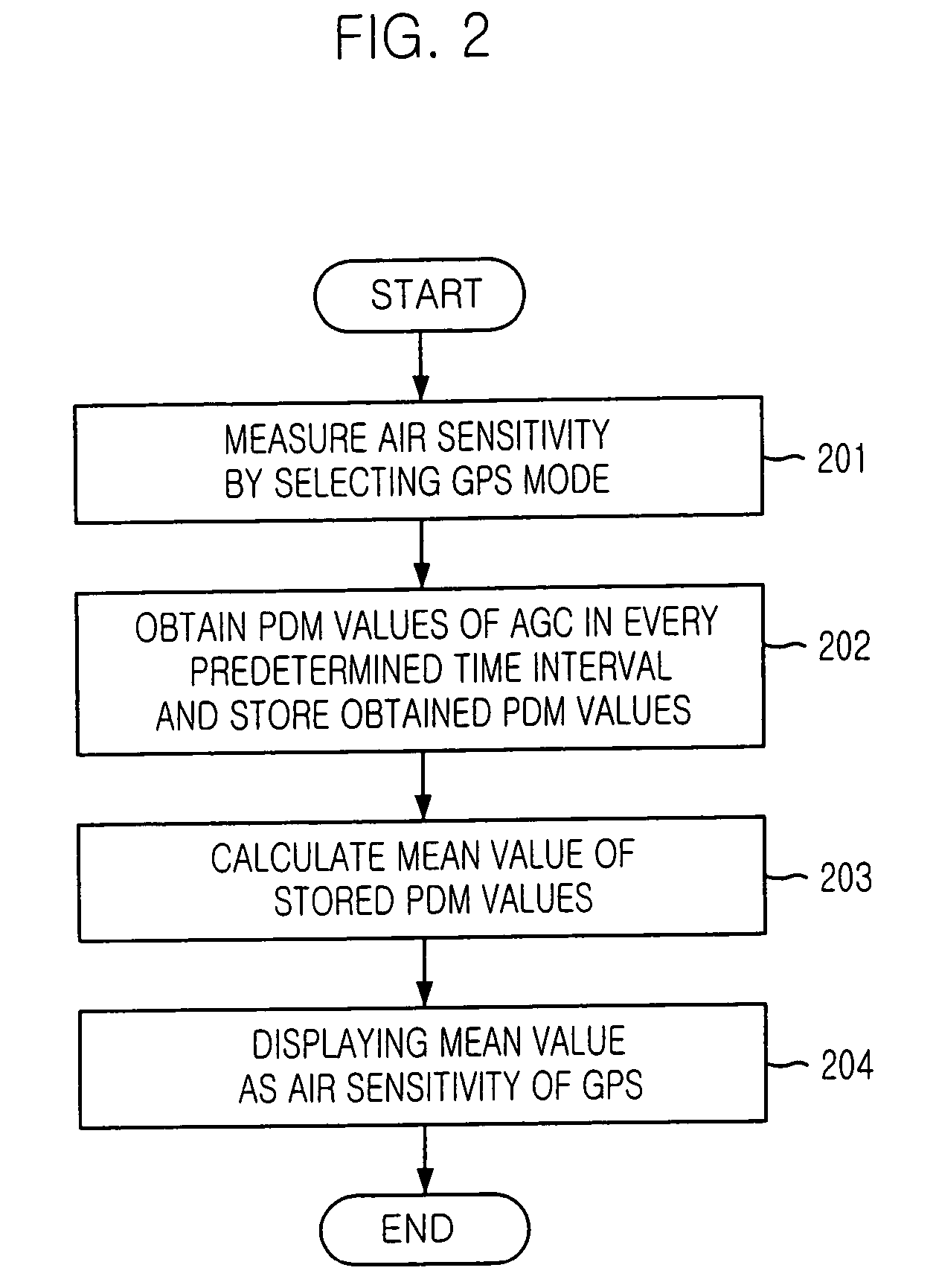
[0017]FIG. 2 is a flow chart of a method for measuring an air sensitivity of global positioning system GPS in a mobile terminal in accordance of a preferred embodiment of the present invention.

[0018]Referring to FIG. 2, a method for measuring air sensitivity of global positioning system in a mobile terminal is explained hereinafter.

[0019]At first, a user starts to operate a mobile terminal to measure air sensitivity by selecting a GPS mode at step S201. The mobile terminal obtains pulse density modulation PDM values of auto gain control AGC amplifier in the mobile terminal within a predetermined time interval and the obtained PDM values are stored at step S202. The PDM values are varied corresponding to strength of GPS signal and it is used for measuring air sensitivity of GPS in the presen...


PUM


Abstract

A method for measuring an air sensitivity of a global positioning system (GPS) signal in a mobile terminal. A GPS signal value is obtained in the mobile terminal. The air sensitivity of the GPS signal value based on a reference GPS signal value is stored in a memory of the mobile terminal, and the air sensitivity of the GPS signal using the analyzed result is displayed on the display unit. A mobile terminal including a controller for obtaining a global positioning system (GPS) signal value is also provided. The terminal also includes a display unit for displaying an air sensitivity of the GPS by using the GPS signal value, and a memory for storing a reference GPS signal value. The controller analyzes the GPS signal value based on the reference GPS signal value, and the display unit displays the air sensitivity of the GPS using the analyzed result.

Description

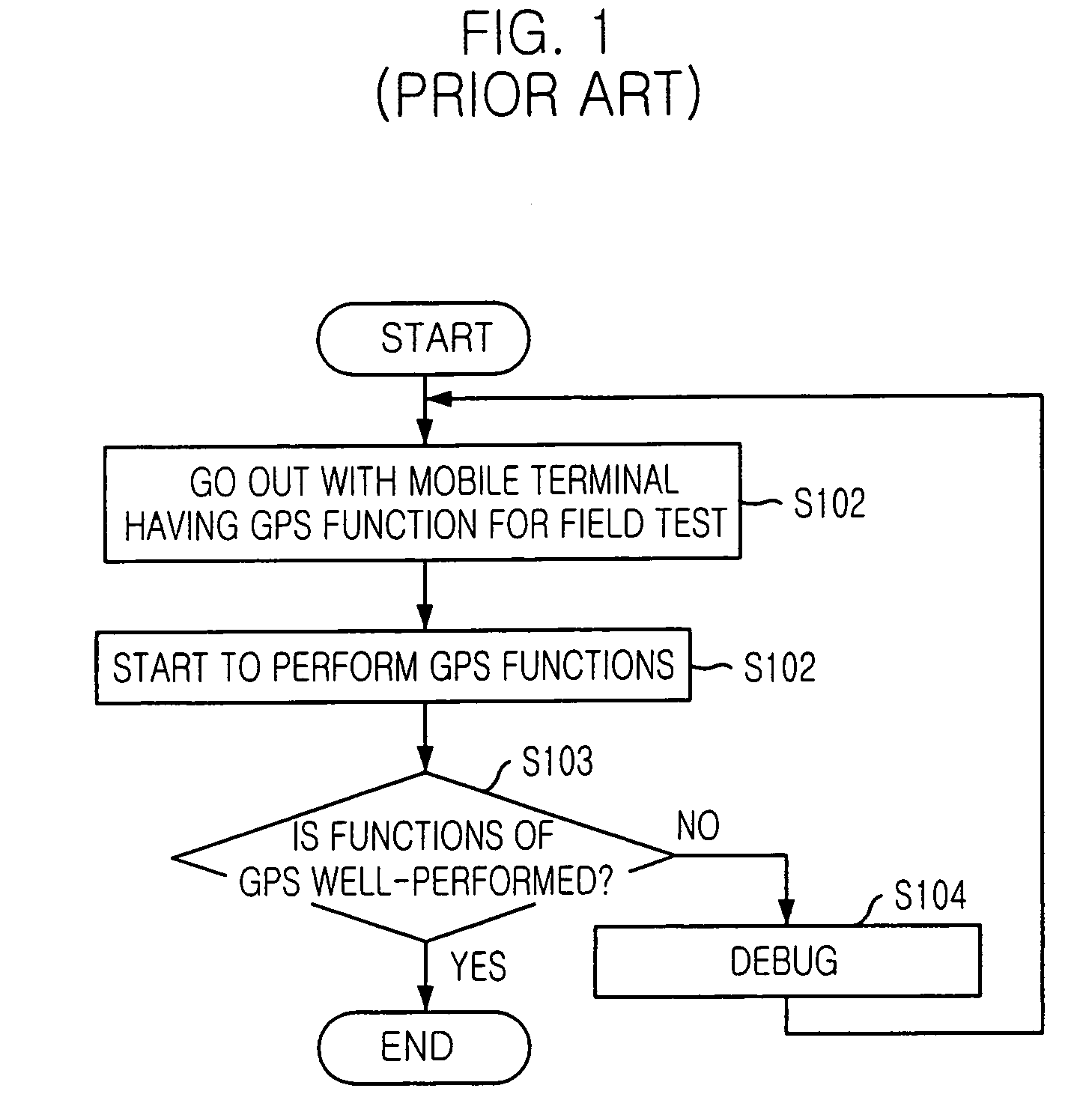
[0001]The present patent application is a Continuation of application Ser. No. 10 / 749,598, filed Dec. 30, 2003 now U.S. Pat. No. 6,784,829.FIELD OF THE INVENTION[0002]The present invention relates to a mobile terminal having a function of measuring air sensitivity of global positioning system GPS and displaying the measured air sensitivity of GPS on a display unit in a mobile terminal.DESCRIPTION OF RELATED ARTS[0003]FIG. 1 is a flow chart showing a conventional method for measuring air sensitivity of global positioning system GPS. In the conventional method, a user carries a mobile terminal having global positioning system GPS and enters a street or a field for a field test to measure air sensitivity of GPS in the mobile terminal at step S101. The user starts to perform functions of GPS in the mobile terminal at step S102. The user determines whether or not the functions of the GPS in the mobile terminal is well-performed by using additional equipment such as a diagnostic monitorin...

Claims


Application Information

Patent Timeline
Patent Type & Authority Patents(United States)
IPC IPC(8): H04B7/185G01S5/02H04B1/16G01S1/00G01S19/23
CPCG01S19/23H04B17/00
Inventor JUNG, KUN-PILLIM, HUN-ILLEE, IN-SUB
Owner PANTECH CORP
Learn More