
Auto-eject gun-lock device with ring-mounted key

a gun-lock device and key-mounted technology, applied in the direction of weapons, weapon components, safety arrangements, etc., can solve the problems of insufficient barrier, inflicting damage to both, and failure of the chamber-engaging arrangemen

Inactive Publication Date: 2006-12-19
HA DON DONGCHO
View PDF13 Cites 14 Cited by
  • Summary
  • Abstract
  • Description
  • Claims
  • Application Information

AI Technical Summary

Benefits of technology

"The present invention is a gun-lock device that can be quickly unlocked without requiring high levels of manual dexterity or remembering the preset combination. The device is designed to be easily operated with a key that can be worn on a ring and quickly accessed with a hand on the gun. The key can be easily inserted into the lock mechanism and the device unlocked by simply moving the hand in the appropriate position. The invention achieves a better chamber-engaging arrangement compared to prior art devices, as it uses a dummy cartridge and a spring-loaded tumbler cylinder to securely lock the chamber. The invention is a significant improvement over existing gun-lock devices."

Problems solved by technology

Because of the small difference between the bore and the chamber diameters of most modern gun designs, the width of this edge is very narrow and thus cannot sufficiently provide as a barrier means to prevent the gun-lock device from being pulled out from the chamber through the bore of the firearm.
With force exerted during an unauthorized removal attempt, the parts of the gun-lock device engaging with the narrow edge, the narrow edge itself, and / or the body of the lock-device may breakdown and cause the chamber-engaging arrangement to fail.
A forced tamper attempt would likely to inflict damage to both the handgun and the prior art gun-lock device, and ultimately may result in an inadvertent removal of the device from the handgun.

Method used


Image

  • Auto-eject gun-lock device with ring-mounted key
  • Auto-eject gun-lock device with ring-mounted key
  • Auto-eject gun-lock device with ring-mounted key

Examples


Embodiment Construction

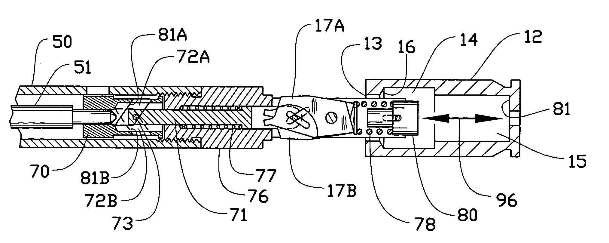
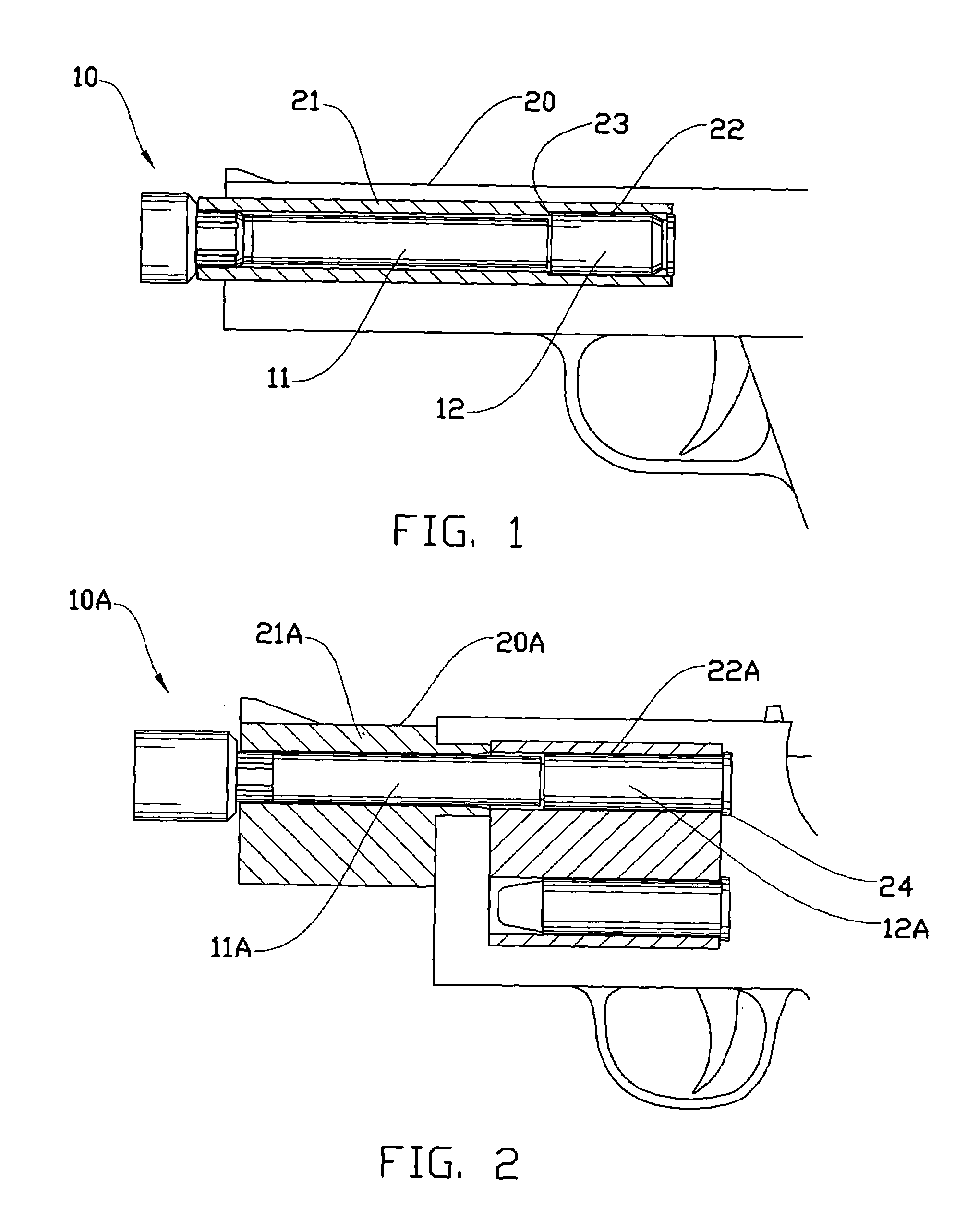
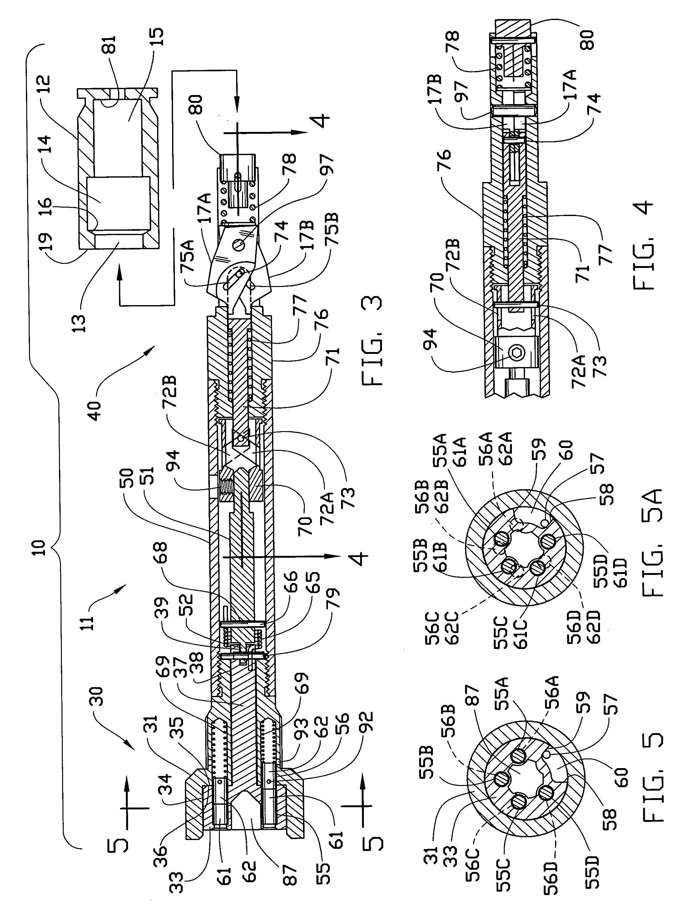
[0038]FIGS. 1–16 of the drawings illustrate various aspects of a gun-lock device 10 constructed according to the invention. Although the following discussions may reference specific features and functions of a large-bore semi-automatic handgun, the inventive concepts disclosed and claimed are not restricted to such. A gun-lock device constructed according to the invention may be configured for use with any handgun or a long gun of semi-automatic, revolver, or of other action type of any caliber size, so as long as the firearm has a barrel with a bore and a chamber.

[0039]The gun-lock device 10 of FIG. 1 includes a tubular assembly 11 which is inserted from the muzzle end of the barrel 21 of the firearm 20 and a chamber plug member 12 which is inserted into the chamber 22 from the breach end of a semi-automatic handgun of such caliber as .40 S&W. The gun-lock device 10A of FIG. 2 is a variation adapted to work with a revolver of such caliber as .357 Magnum, wherein a tubular assembly ...


PUM


Abstract

A gun-lock device includes a tubular assembly that fits within the bore and a chamber plug member that fits within the chamber of a firearm. The tubular assembly is partially received into the chamber plug member, wherein spring-loaded expandable arrangement at the end thereof engages with the recess within the chamber plug member to lock the tubular assembly within the barrel. The lock subassembly includes a tumbler cylinder arranged to rotate about the longitudinal axis of the tubular assembly and a set of lock-pins which are disposed parallel to, and in a circular formation about, the longitudinal axis of the tumbler cylinder. The resulting overall arrangement yields a compactly packaged gun-lock device suitable for use in combination with a holster-worn firearm, and the key, with such small size and ornate shape, suitable for being mounted on a ring to be worn by the user at all times. A spring loaded plunger mechanism enhances the speed and ease of operation by adding a self-eject feature to the device.

Description

REFERENCES CITED (REFERENCED WITHIN THE SPECIFICATION)[0001]4398366August 1983Wernicki4512099April 1985Mathew5289653March 1994Szebeni et al.5475994December 1995Briley, Jr. et al.5491918February 1996Elmstedt5664358September 1997Haber et al.5860241January 1999Waters6560910May 2003McLarenCROSS-REFERENCE TO RELATED APPLICATIONS[0002]Not applicable.BACKGROUND OF THE INVENTION[0003]1. Technical Field[0004]This invention relates to a safety gun-lock device for firearms, and more particularly for handguns for preventing unauthorized use, yet allow speedy unlocking and removal of the gun-lock device for authorized use of the firearm.[0005]2. Description of the Related Art[0006]Several of existing gun-lock devices are made in the form of a “barrel lock”, wherein a tubular body portion of the gun-lock device is inserted into the barrel and the firing chamber portions of the firearm and is locked in position to render the firearm inoperative until such device is removed. This type of device gen...

Claims


Application Information

Patent Timeline
Patent Type & Authority Patents(United States)
IPC IPC(8): F41A17/00
CPCF41A17/44
Inventor HA, DON DONGCHO
Owner HA DON DONGCHO
Learn More