
Underwater surveillance system

a surveillance system and underwater technology, applied in mine sweeping, instruments, offensive equipment, etc., can solve the problems of unsuitable targets for surveillance systems involving long-range acoustic and magnetic target detection

Inactive Publication Date: 2006-12-12
MCDONNELL THOMAS
View PDF2 Cites 17 Cited by
  • Summary
  • Abstract
  • Description
  • Claims
  • Application Information

AI Technical Summary

Benefits of technology

[0004]Pursuant to the present invention, sensing modules are positioned underwater at preselected sea water locations to establish targeted surveillance zones within which magnetic and electric sensing fields are established for detection limited to targets such as relatively small submarines within shallow depth target zones. According to certain embodiments of the present invention, the sensing modules are

Problems solved by technology

Such prior surveillance systems involving long range acoustic and magnetic target detection are often unsuitable for targets such as small sea vessels in shallow water environments.

Method used


Image

  • Underwater surveillance system
  • Underwater surveillance system
  • Underwater surveillance system

Examples


Embodiment Construction

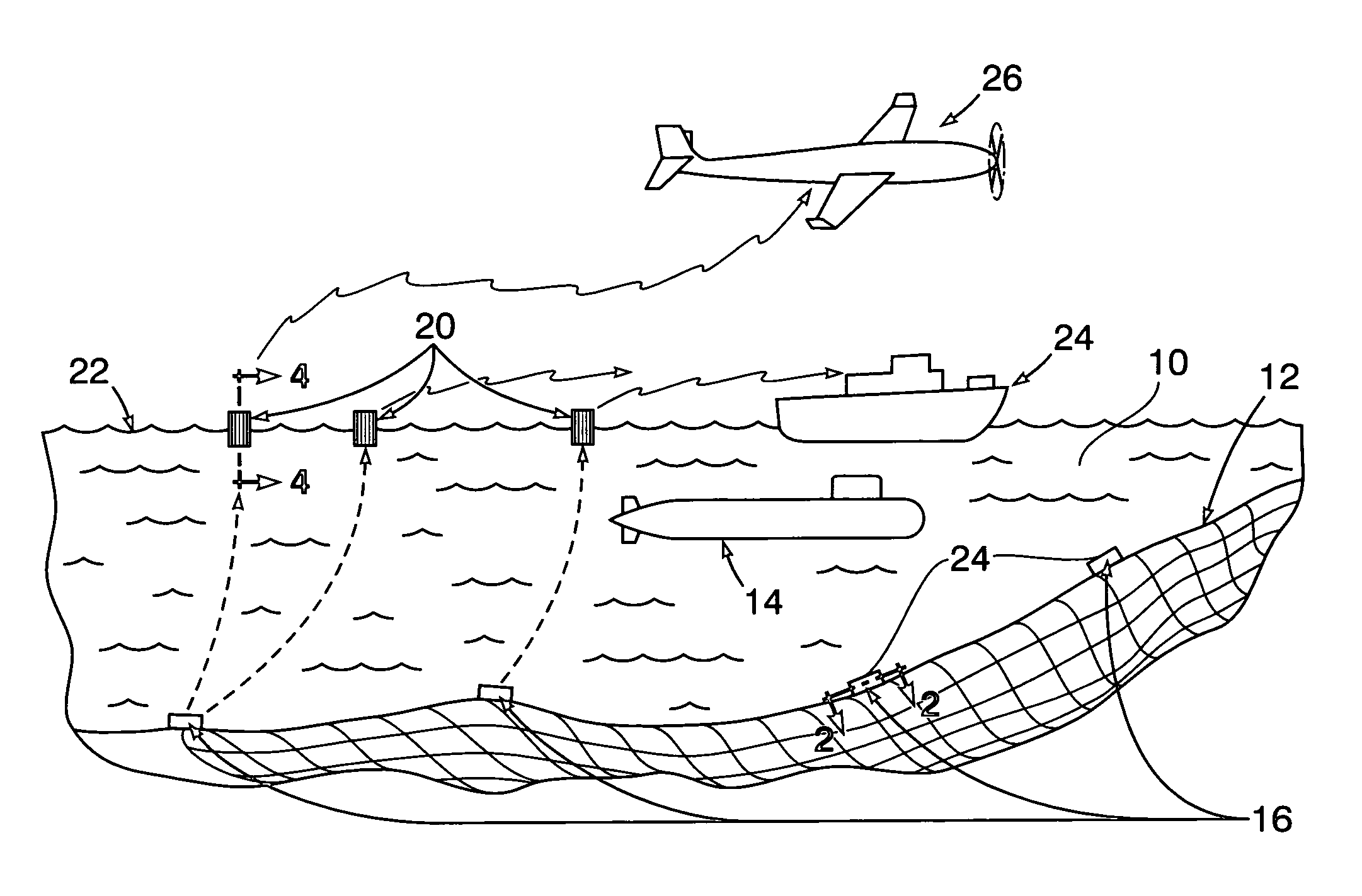
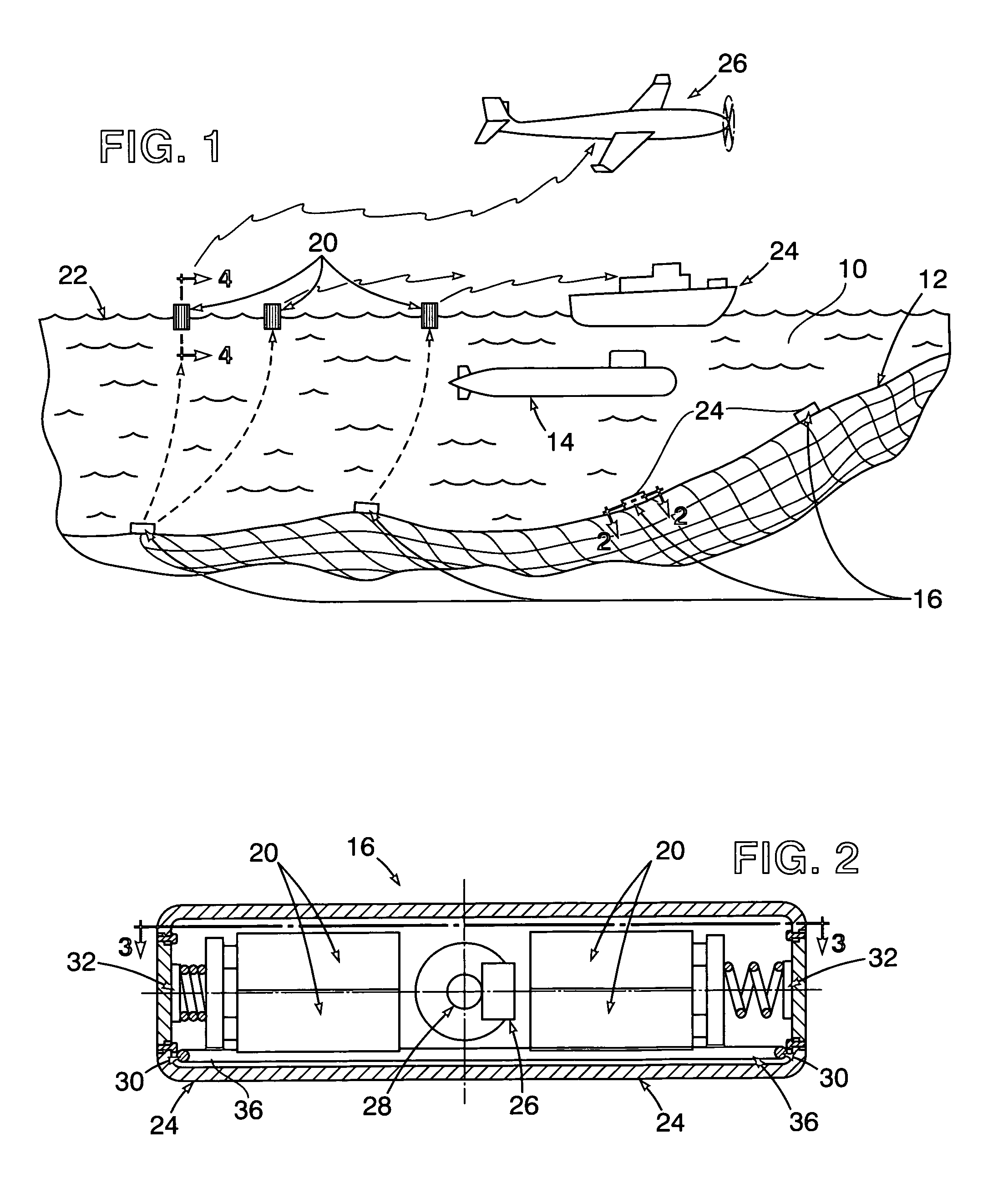
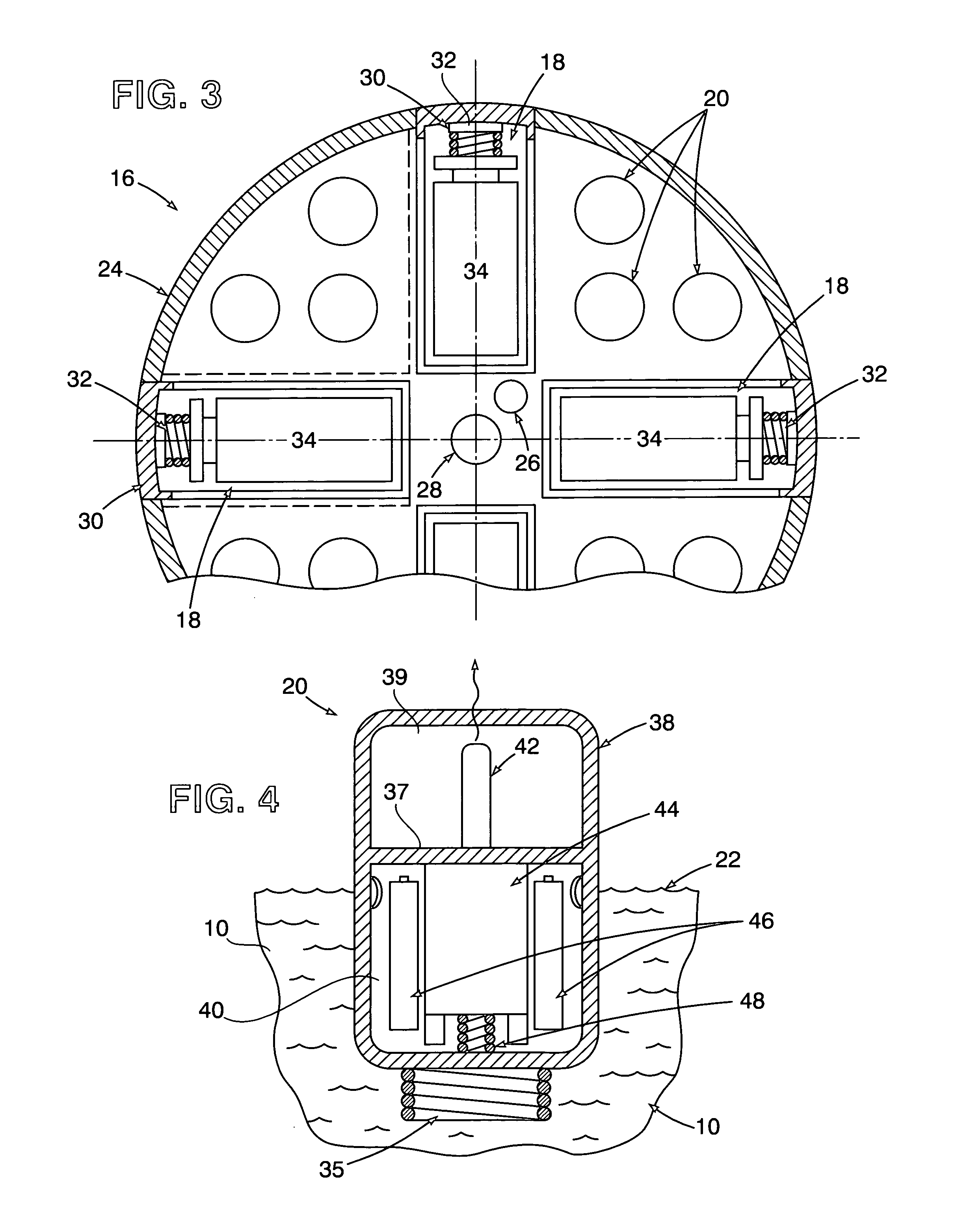
[0011]Referring now to the drawing in detail, FIG. 1 illustrates a body of seawater 10 having a shallow depth of less than 300 meters above a seafloor surface 12. A submarine target 14 is shown in the body of seawater 10 under surveillance within a target zone established by positioning of underwater sensor modules 16 in spaced relation to each other on the seafloor surface 12. Detection of the target 14 within such target zone is effected by means of a surveillance system associated with the aforesaid array of the underwater sensor modules 16 from which transmitters 20 are ejected and rise to floating level positions at seawater surface 22 as shown in FIG. 1. Once detection of the target 14 by one of the underwater sensor modules 16 has been effected, the transmitters 20 are ejected therefrom, as hereinafter explained, so as to float to the top seawater surface level 22 in response to data signals transmitted at radio frequencies from manned or unmanned data receiving vehicles, suc...


PUM


Abstract

A plurality of sensing modules are deployed by positioning thereof in spaced relation to each other on a seafloor surface at a shallow depth to establish a targeted seawater zone within which certain conditions are detected, such as those produced by the presence of a sea vessel such as a submarine within the targeted zone. Data signals are generated within the deployed sensing modules in response to said detection of the submarine for radio frequency transmission above the seawater targeted zone from floating transmitters ejected from the sensing modules positioned on the seafloor surface after detection of the submarine.

Description

[0001]The present invention relates generally to surveillance and collection of data with respect to target zones within a body of seawater involving signal transmission of the data and collection thereof above the seawater surface.STATEMENT OF GOVERNMENT INTEREST[0002]The invention described herein may be manufactured and used by or for the Government of the United States of America for governmental purposes without the payment of any royalties thereon or therefore.BACKGROUND OF THE INVENTION[0003]Surveillance systems have been employed to detect hostile environments such as underwater zones in seawater that are targeted because of corrosion induced by sea vessels. Such systems utilize electronically enhanced magnetic and electric field sensing technologies involving microprocessors to obtain signal surveillance outputs reflecting detection, signature, classification, local positioning and tracking algorithms associated with targets, while discriminating against ambient noise and i...

Claims


Application Information

Patent Timeline
IPC IPC(8): G02B6/00
CPCB63G7/02B63G7/06B63G7/08B63G13/00
Inventor SCARZELLO, JOHN F.HOLMES, JOHN J.O'KEEFE, EDWARD C.WINGO, ROBERT A.
Owner MCDONNELL THOMAS
Learn More