
Structure of flexible printed circuit board

a flexible, circuit board technology, applied in the direction of printing, printing circuit non-printed electric components association, electrical apparatus construction details, etc., can solve the problem of excessive melted solder entering the through hole, and achieve excellent electric properties

Inactive Publication Date: 2006-12-12
BROTHER KOGYO KK
View PDF15 Cites 26 Cited by
  • Summary
  • Abstract
  • Description
  • Claims
  • Application Information

AI Technical Summary

Benefits of technology

The invention provides a circuit board with excellent electric properties. The connection structure between a flexible printed circuit board and a circuit board includes a flexible printed circuit board and a circuit board. The terminal land of the flexible printed circuit board is connected with the terminal land of the circuit board using solder. This structure prevents excessive melted solder from entering the through hole. Additionally, the invention includes a recording apparatus with a flexible printed circuit board and a drive circuit that drives the recording head via the feeder wires. The technical effects of this invention include improved electrical performance and more efficient recording.

Problems solved by technology

When the terminal lands of the flexible printed circuit board and the circuit board are connected with each other, excessive melted solder enters the through hole.

Method used


Image

  • Structure of flexible printed circuit board
  • Structure of flexible printed circuit board
  • Structure of flexible printed circuit board

Examples


Embodiment Construction

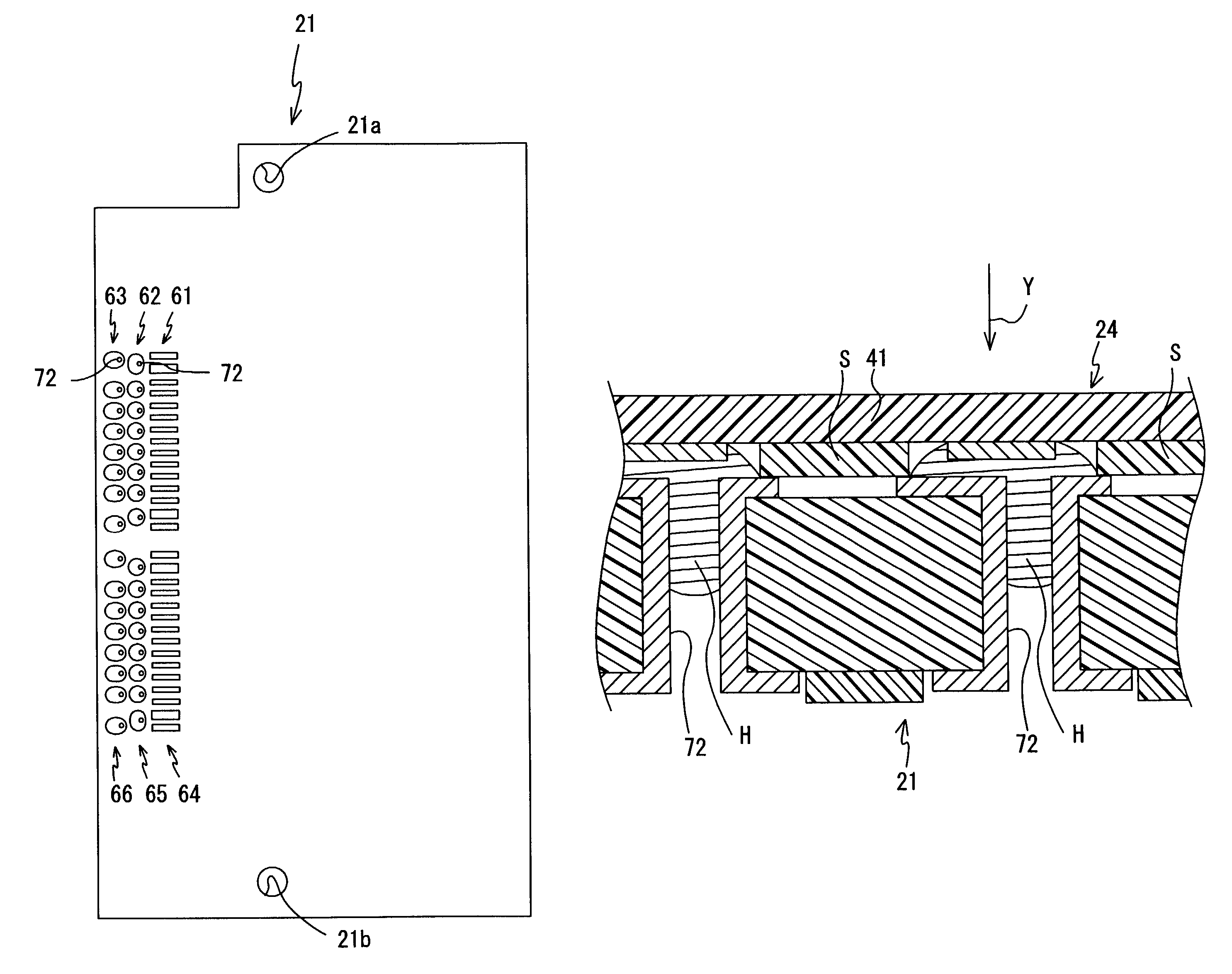
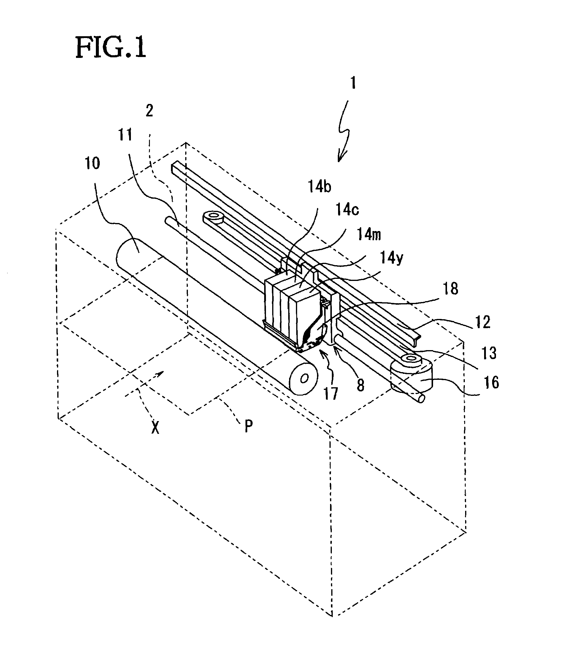
[0031]An exemplary embodiment of a recording apparatus of the invention will be described with reference to the accompanying drawings. First, referring to FIG. 1, an internal structure of an ink-jet printer 1 will be described.

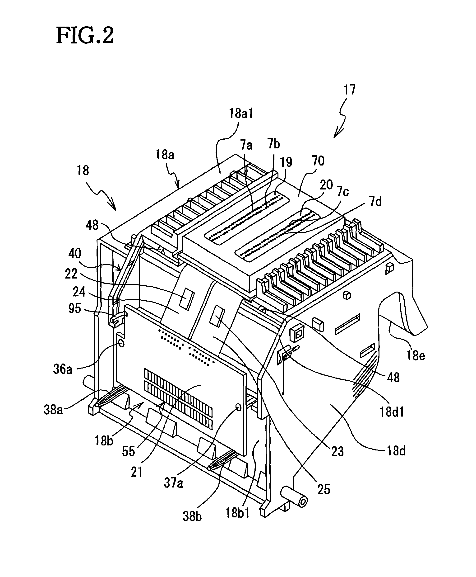
[0032]As shown in FIG. 1, the ink-jet printer 1 includes a housing 2. In the housing 2, a carriage 8 is slidably supported by a guide rod 11 and a guide member 12 and fixedly attached to a belt 13 so as to reciprocate by a carriage (CR) motor 16. A printhead unit 17, having printheads 19, 20 (see FIG. 2) for performing printing, is attached to the carriage 8. The printheads 19, 20 are ink-jet printheads that perform printing on a recording sheet P, as a recording medium, by ejecting ink droplets of four different color inks (cyan c, magenta m, yellow y, and black b). Nozzle rows 7a, 7b are provided in the printhead 19 and other nozzle rows 7c, 7d are provided in the printhead 20 (see FIG. 2), so as to face the recording sheet P. The black ink b, cyan ink c, ma...


PUM

PropertyMeasurementUnit
flexibleaaaaaaaaaa
surface areaaaaaaaaaaa
circuit structureaaaaaaaaaa

Abstract

A recording apparatus that has a recording head and a flexible printed circuit board. The recording head, which performs recording on a recording medium, has a plurality of recording elements. One end of the flexible printed circuit board has plurality of feeder wires that connect to one of the terminal lands of each of the recording elements. A first common voltage wire connects the other terminal lands of each of the recording elements to a common potential. A drive circuit is attached to the flexible printed circuit board to drive the recording head via the feeder wires. The other end of the flexible printed circuit board is connected to another circuit board used by the recording apparatus.

Description

BACKGROUND OF THE INVENTION[0001]1. Field of Invention[0002]The invention relates to a structure of circuit boards.[0003]2. Description of Related Art[0004]A flexible printed circuit board has been used in electronic equipment to supply power and signals therein. The flexible printed circuit board connects two circuit boards or parts, to each other, passing through a narrow portion or a zigzag path, so that the circuit boards and parts can be placed at any location. Accordingly, the flexible printed circuit board offers design freedom in electronic equipment, and particularly, saves an amount of a wasted space, thereby downsizing the equipment. The flexible printed circuit board is provided with an IC chip and a circuit connecting the IC chip. However, the conventional flexible printed circuit board may not have sufficient electric properties.SUMMARY OF THE INVENTION[0005]It is therefore an object of the invention to provide a circuit board having excellent electric properties.[0006...

Claims


Application Information

Patent Timeline
Patent Type & Authority Patents(United States)
IPC IPC(8): H05K1/18B41J2/14H05K1/11H05K3/34H05K3/36H05K7/14
CPCB41J2/14209H05K3/363B41J2002/14491H05K1/116H05K3/3452Y10T29/49126H05K2201/09381H05K2201/09409H05K2203/0455
Inventor SUZUKI, SHIGERUKATO, YASUHIROKUBO, TOMOYUKIIMAI, KOJI
Owner BROTHER KOGYO KK
Learn More