
Insulated cable attachment device

a technology of insulating cable and terminator, which is applied in the direction of coupling device connection, television connector, two-part coupling device, etc., can solve problems such as electric shock, and achieve the effect of preventing any difference in ground potential

Active Publication Date: 2006-12-05
PPC BROADBAND INC
View PDF28 Cites 22 Cited by
  • Summary
  • Abstract
  • Description
  • Claims
  • Application Information

AI Technical Summary

Benefits of technology

[0004]Briefly stated, an insulated cable attachment device, made of an electrically insulating material, is connectable to a termination connector which is in turn connectable to a tap port for a cable television system. When an installer disconnects service to a subscriber's house, the signal is shut down to the tap port to which the subscriber drop cable is connected. The drop cable is disconnected from the tap port and a terminator connector is connected in its place on the tap port. The installer then installs the insulated cable attachment device onto the terminator connector before connecting the drop cable to the insulated cable attachment device, thereby preventing any difference in ground potentials between the terminal connector and the drop cable from being transmitted to the end of the drop cable near the house.
[0007]According to an embodiment of the invention, a method for preventing electrical shock in a cable television system includes the steps of shutting down a signal to a tap port; disconnecting a drop cable from the tap port; installing a terminator connector on the tap port; installing an insulated cable attachment device on the terminator connector; and connecting the drop cable to the insulated cable attachment device, thereby preventing a potential difference between a ground potential on the terminal connector and a ground potential on the drop cable from being transmitted to an installer.

Problems solved by technology

Thus, connecting the drop cable to the terminator connector can result in an electric shock as current flows from one level of ground to another.

Method used


Image

  • Insulated cable attachment device
  • Insulated cable attachment device
  • Insulated cable attachment device

Examples


Embodiment Construction

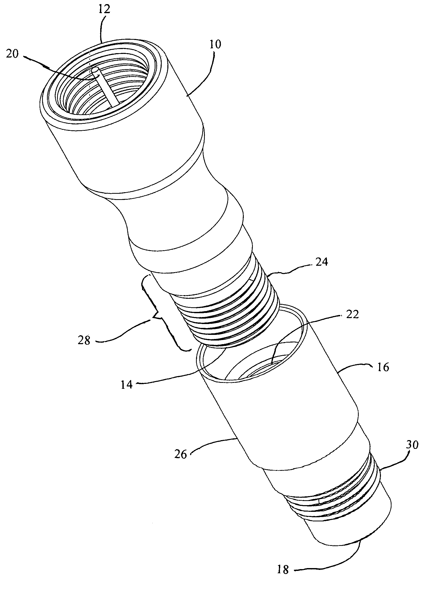
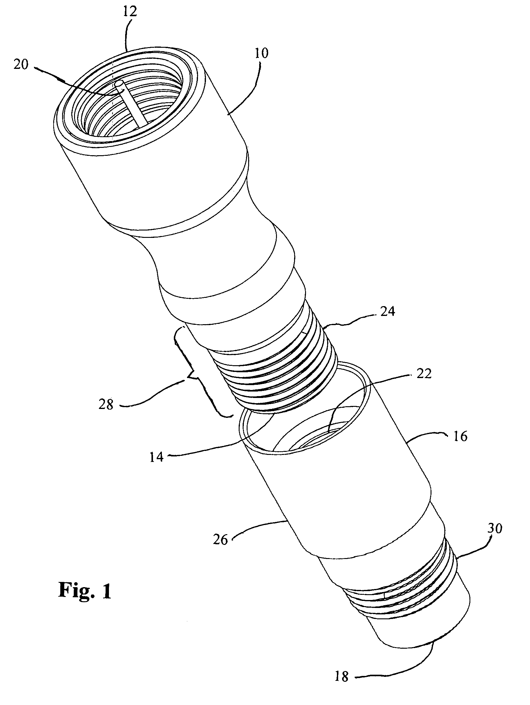
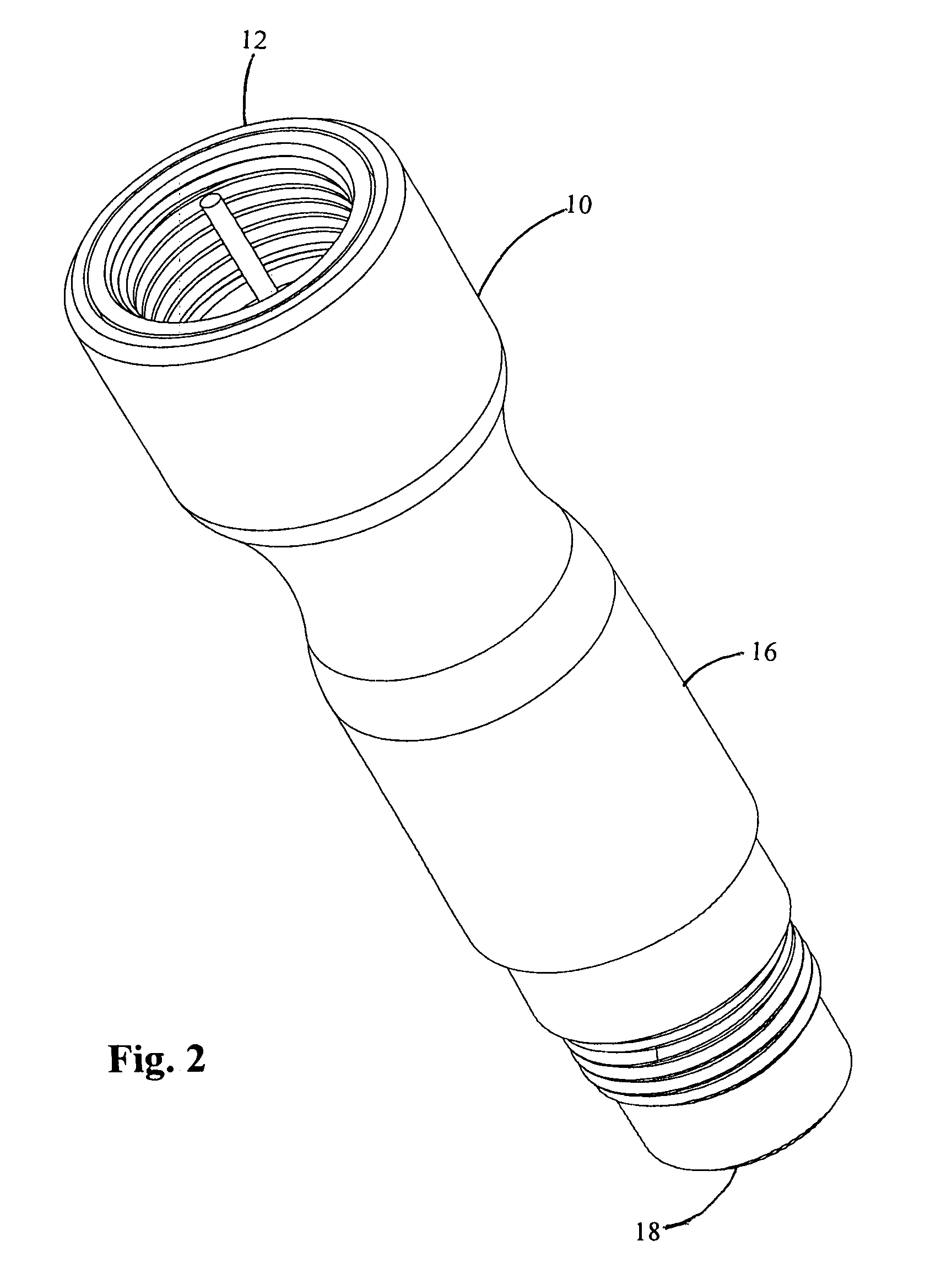
[0013]Referring to FIGS. 1–4, a conventional 75 ohm terminator connector 10 includes an end 12 which is internally threaded to fit into a tap port (not shown). A conductive pin 20 connects with a corresponding hole in the tap port. The impedance between conductive pin 20 and the outside of terminator connector 10 appears as 75 ohms to the tap port. There is no direct electrical connection between conductive pin 20 and a center conductive wire within a coaxial cable (not shown) or a center conductor of a connector on the coaxial cable when the coaxial cable is connected to terminator connector 10 as is the conventional practice.

[0014]An insulator 16, preferably of DELRIN®, includes a plurality of internal threads 22 which correspond to a plurality of external threads 24 on an end 14 of terminator connector 10. Insulator 16 includes a main portion 26 which covers a bottom portion 28 of terminator connector 10 when insulator 16 is screwed onto terminator connector 10. A plurality of ex...


PUM


Abstract

An insulated cable attachment device, made of an electrically insulating material, is connectable to a termination connector which is in turn connectable to a tap port for a cable television system. When an installer disconnects service to a subscriber's house, the signal is shut down to the tap port to which the subscriber drop cable is connected. The drop cable is disconnected from the tap port and a terminator connector is connected in its place on the tap port. The installer then installs the insulated cable attachment device onto the terminator connector before connecting the drop cable to the insulated cable attachment device, thereby preventing any difference in ground potentials between the terminal connector and the drop cable from being transmitted to the end of the drop cable near the house.

Description

FIELD OF THE INVENTION[0001]This invention relates generally to the field of devices used with CATV systems, and more particularly to an insulated terminator connector.BACKGROUND OF THE INVENTION[0002]Cable TV (CATV) distribution systems move a cable signal to a tap near a subscriber's house. When a cable installer shuts down service from a subscriber, a 75 ohm terminator connector is installed onto the tap port which is on the telephone / cable pole. One end of the terminator connector screws into the tap port, after which the drop cable from the house of the subscriber to the pole is then connected to the other end of the terminator connector.[0003]The ground of the drop cable is electrically bonded to the ground potential in the house of the subscriber. It is possible that this ground potential is different than the ground potential at the tap. Thus, connecting the drop cable to the terminator connector can result in an electric shock as current flows from one level of ground to an...

Claims


Application Information

Patent Timeline
Patent Type & Authority Patents(United States)
IPC IPC(8): H01R9/05
CPCH01R13/60H01R24/44H01R24/542H01R2103/00H01R2201/18
Inventor CHAWGO, SHAWN
Owner PPC BROADBAND INC
Learn More