
Coaxial cable connector with threaded outer body

a technology of coaxial cable connector and outer body, which is applied in the direction of line/current collector details, coupling contact members, electrical equipment, etc., can solve the problems of difficult if not impossible insertion of prepared coaxial cable into typical f-connector, extreme difficulty in terminating hec coaxial cable, and close to impossible,

Active Publication Date: 2006-12-05
PPC BROADBAND INC
View PDF15 Cites 104 Cited by
  • Summary
  • Abstract
  • Description
  • Claims
  • Application Information

AI Technical Summary

Problems solved by technology

The multiple layers of conductive grounding foil and braided shield cause the HEC cable to have a larger diameter than the typical coaxial cables, thereby making insertion of the prepared coaxial cable into the typical F-connectors difficult if not impossible.
Thus, the termination of the HEC coaxial cables is extremely difficult, if not close to impossible, using standard techniques and materials.
While a larger coaxial cable connector may solve the problem, it would also increase the number of connectors that the tradesmen would need to stock, causing potential confusion, increased capital expenditures, and potential damage to those connectors if they are used incorrectly (on coaxial cables that are not HEC, for example).

Method used


Image

  • Coaxial cable connector with threaded outer body
  • Coaxial cable connector with threaded outer body
  • Coaxial cable connector with threaded outer body

Examples


Embodiment Construction

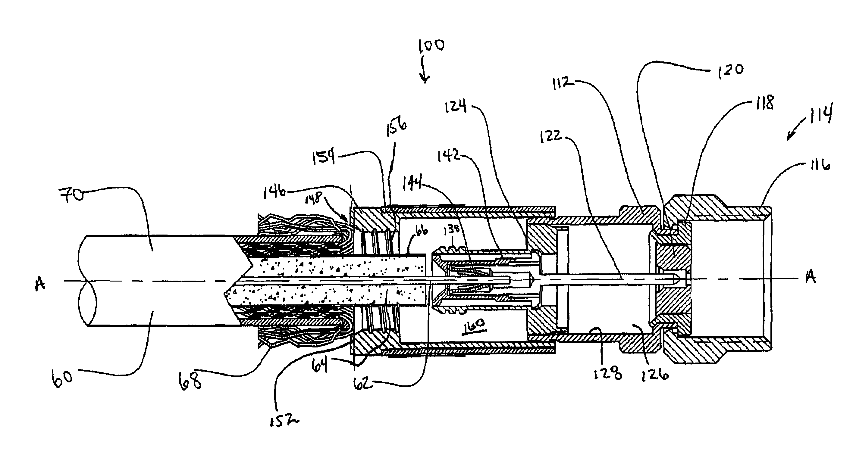
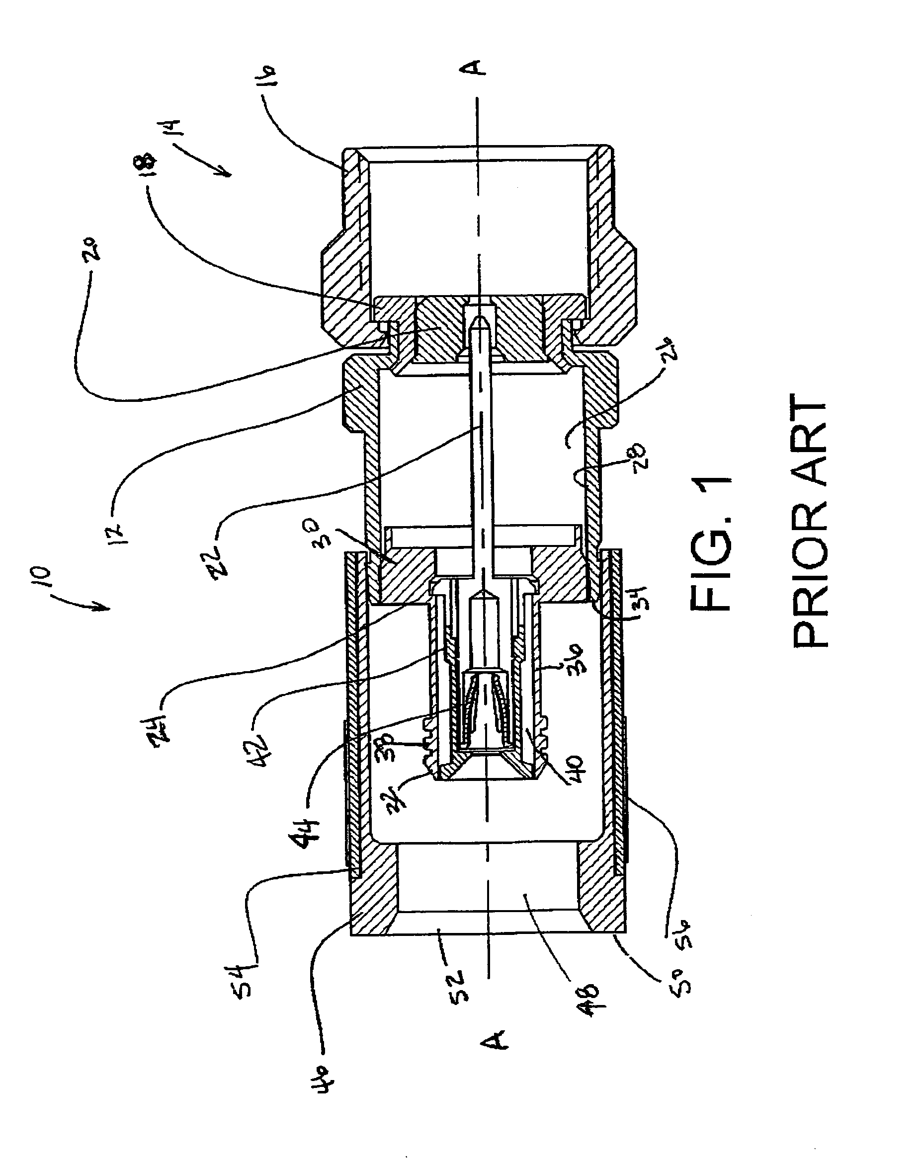
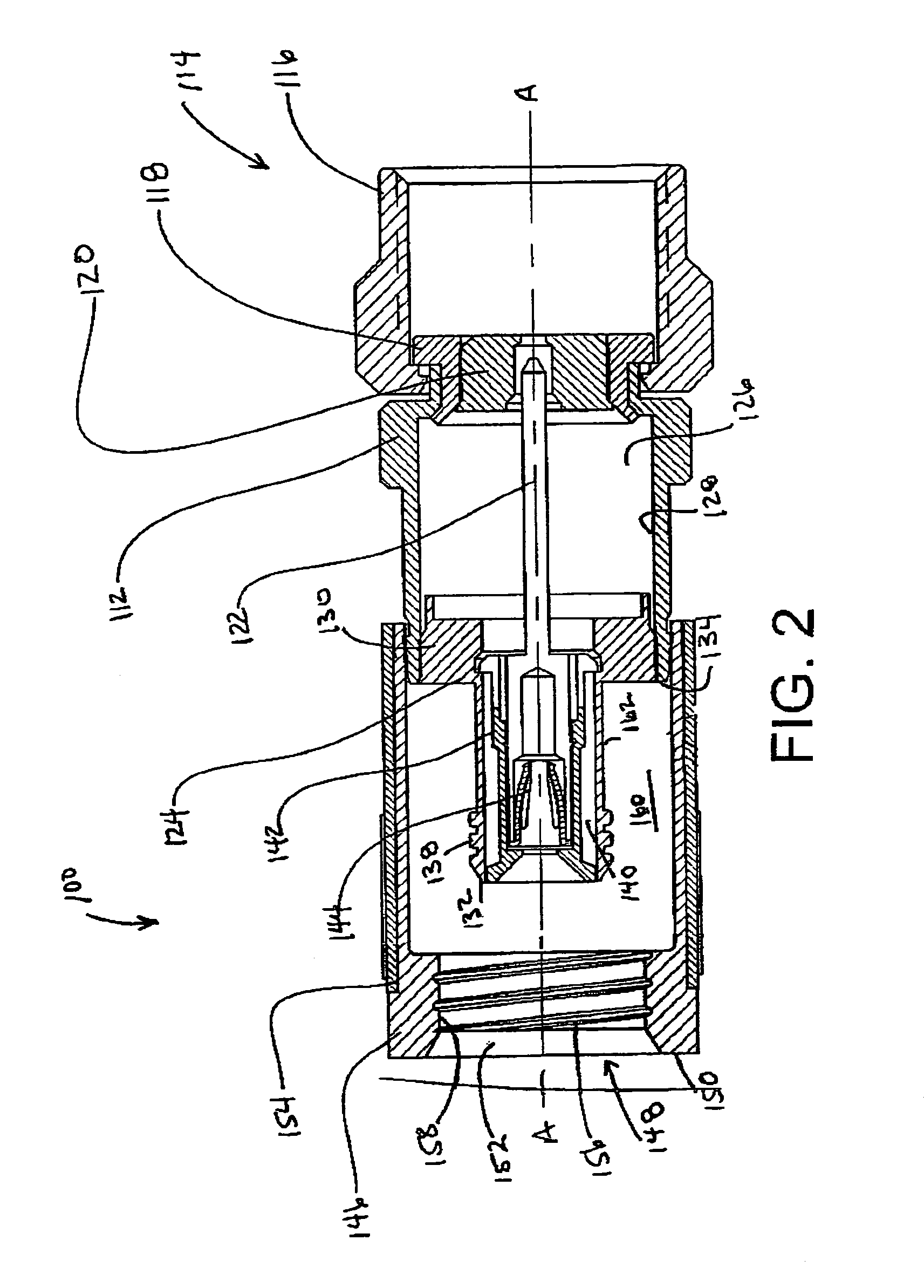
[0029]Reference will now be made in detail to the present preferred embodiment(s) of the invention, examples of which are illustrated in the accompanying drawings. Whenever possible, the same reference numerals will be used throughout the drawings to refer to the same or like parts. One embodiment of the present invention is shown in FIG. 2 and is designated generally throughout by the reference numeral 100.

[0030]FIG. 1 schematically illustrates a coaxial cable connector 10 according to the prior art. FIG. 2 schematically illustrates one preferred embodiment of a coaxial cable connector 100, as disclosed herein, in an open configuration. FIGS. 3–7 illustrate the coaxial cable connector 100 and the insertion onto a coaxial cable 60 in greater detail. FIG. 8 illustrates an alternative embodiment of the coaxial cable connector in FIG. 2. FIGS. 9–14 illustrate an alternative embodiment of a coaxial cable connector according to the present invention. FIGS. 15–16 illustrate another altern...


PUM


Abstract

A connector for coaxial cable is disclosed herein that has an outer body, the outer body has at least one thread on a rearward portion thereof, and tubular post having at least one projection thereon. The outer body and the tubular post are movable relative to one another to compress a portion of the coaxial cable in the connector and to draw the braided shield of the coaxial cable into the connector. The present coaxial connector accommodates coaxial cables with larger amounts of braided shielding. A related method for connecting the coaxial cable and connector is also disclosed.

Description

BACKGROUND OF THE INVENTION[0001]1. Field of the Invention[0002]The present invention relates generally to coaxial cable connectors, and particularly to coaxial drop cable connectors capable of being connected to a terminal.[0003]2. Technical Background[0004]Coaxial cable connectors such as F-connectors are used to attach coaxial cables to another object such as an appliance or junction having a terminal adapted to engage the coaxial cable connector. Coaxial cable F-connectors are often used to terminate a drop cable in a cable television system. The coaxial cable typically includes a center conductor surrounded by a dielectric, in turn surrounded by a conductive grounding foil and / or braided shield; the conductive grounding foil and / or braided shield are in turn surrounded by a protective outer jacket. The F-connector is secured over the prepared end of the jacketed coaxial cable, allowing the end of the coaxial cable to be connected with a terminal block, such as by a threaded con...

Claims


Application Information

Patent Timeline
IPC IPC(8): H01R9/05
CPCH01R9/05H01R13/59H01R13/03H01R43/28
Inventor BURRIS, DONALD A.LUTZ, WILLIAM B.
Owner PPC BROADBAND INC
Learn More