
Image processing system

a processing system and image technology, applied in the field of image processing system, can solve the problems of long time required for pressing shutter, and insufficient performance of general-purpose cpu, and achieve the effect of small dissipation power

Inactive Publication Date: 2006-11-28
NEC CORP
View PDF3 Cites 80 Cited by
  • Summary
  • Abstract
  • Description
  • Claims
  • Application Information

AI Technical Summary

Benefits of technology

[0006]In view of the foregoing, it is an object of the present invention in order to overcome the above-mentioned problem, to provide an image processing system whose circuit scale is small, and whose dissipation power is small.

Problems solved by technology

In the video camera, when the moving image processing is executed using general-purpose CPU, in a lot of cases, performance of the general-purpose CPU is insufficient.
However, in the conventional image processing system, there are following some problems to be achieved.
In such the cases, there is the problem that it is required long time from pressing the shutter until the end of processing in comparison with the case of the silver-chloride film camera.
Another problem occurs that it is necessary to use a large quantity of memories.
However, there is the problem that dissipation power per pixel is large in comparison with the case of dedicated wired logic processing device whose parallel processing property is high.
However, it is difficult for the general purpose CPU to cause an operation circuit to be operated simultaneously in parallel.
Thus, energy efficiency deteriorates in comparison with the wired logic processing device.
In the video camera, there is a problem that the design of dedicated wired logic device for the moving image processing becomes longer than developing interval of program of the general-purpose CPU.
It takes long time for designing and manufacturing the dedicated wired logic processing device.
On the other hand, the dedicated wired logic processing device is difficult to halt operation, so that it is difficult to discover problem on processing.

Method used


Image

  • Image processing system
  • Image processing system
  • Image processing system

Examples


Embodiment Construction

[0028]A preferred embodiment of the present invention will now be described in detail in accordance with the accompanying drawings.

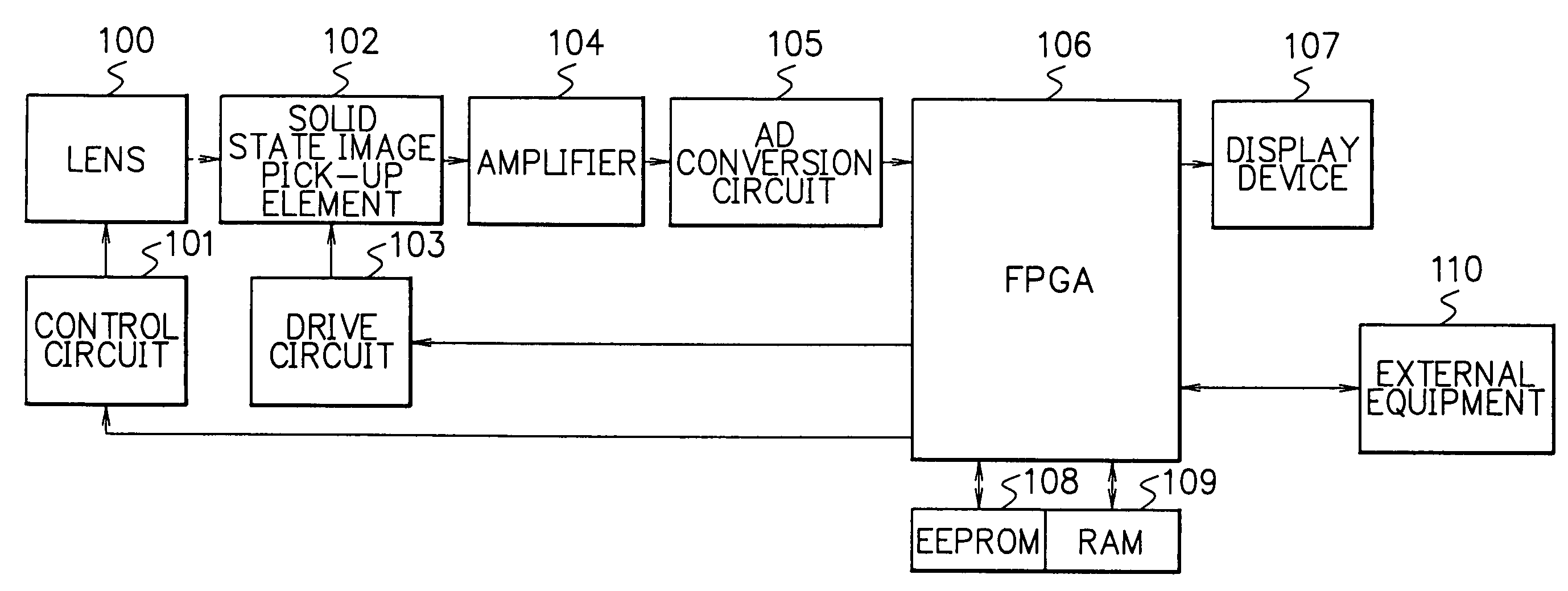
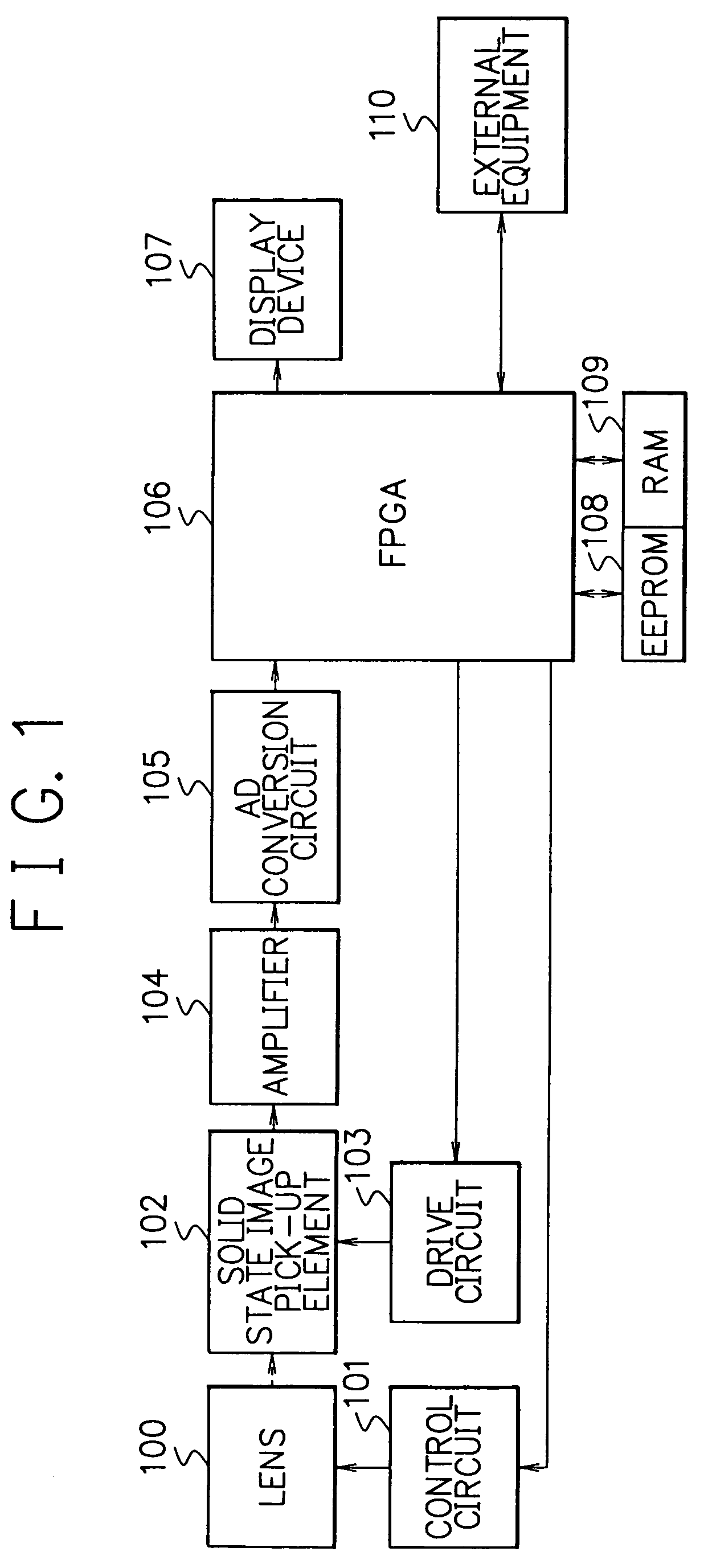
[0029]FIG. 1 is a block diagram showing an image processing system as a first embodiment of the present invention. As shown in FIG. 1, the image processing system as one embodiment of the present invention comprises a lens 100, a control circuit 101, a solid state image pick-up element 102, a drive circuit 103, an amplifier 104, an AD conversion circuit 105, an FPGA (Field Programmable Gate Array) 106, a display device 107, a storage device 108 such as EEPROM (Electrically Erasable Programmable Read-Only Memory), an RAM (Random Access Memory) 109, and an external equipment 110.

[0030]A light permeates the lens 100. The permeated light undergoes photoelectric conversion at the solid state image pick-up element 102. The lens 100 is controlled by the control circuit 101. The solid state image pick-up element 102 is driven by the drive circuit 103. The amplif...


PUM


Abstract

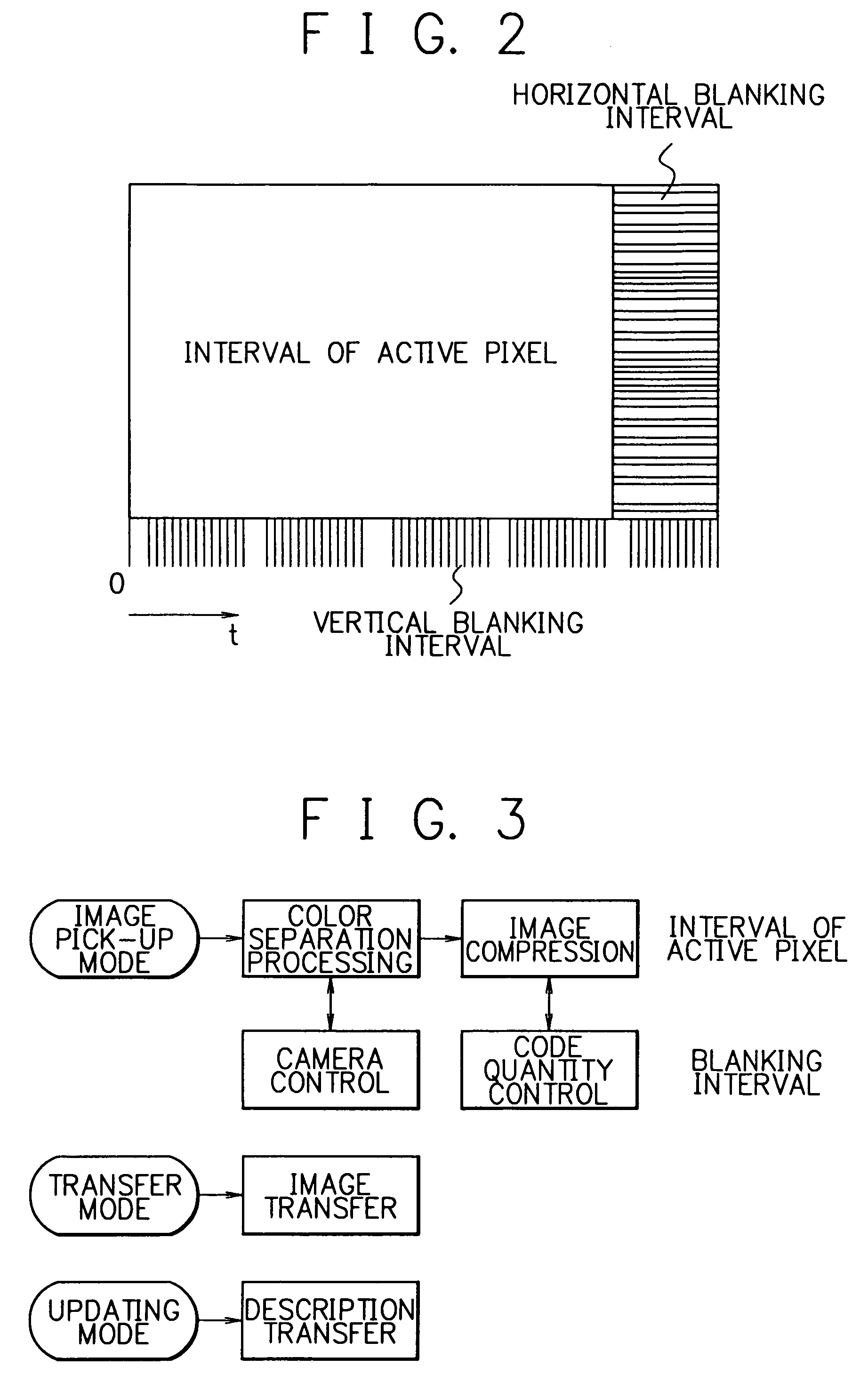
An image processing system whose circuit size is small, and whose dissipation power is small is provided. The image processing system executes digital image processing of an interval of active pixel in the condition that a first internal logic description is written in a field programmable gate array. Subsequently, in interval of non-active pixel with the exception of the interval of active pixel, the image processing system executes digital control processing in the condition that the first internal logic description of the field programmable gate array is rewritten to a second internal logic description. The image processing system executes again the digital image processing in the condition that the second internal logic description of the field programmable gate array is rewritten to the first internal logic description.

Description

BACKGROUND OF THE INVENTION[0001]The present invention relates to an image processing system for processing an image data.DESCRIPTION OF THE PRIOR ART[0002]In the conventional digital still camera or the video camera uses an image pick-up element. The digital still camera and / or the video camera executes digital conversion of an output signal from the image pick-up element. The digital-converted image signal is inputted to a general-purpose CPU or a wired logic processing device. The general purpose CPU or the wired logic processing device executes an image processing such as color separation processing and / or image compression processing. A lot of digital still camera execute digital image processing so as to be able to alter processing system of the image easily by using the general-purpose CPU. On the other hand, the video camera requires high speed moving image processing device. In the video camera, when the moving image processing is executed using general-purpose CPU, in a lo...

Claims


Application Information

Patent Timeline
Patent Type & Authority Patents(United States)
IPC IPC(8): G06K9/54H04N5/235H04N7/08H04N5/14G06T1/00G06T1/20H04N5/52H04N7/24H04N19/00H04N19/42H04N19/46H04N19/625H04N19/70H04N19/85H04N19/91H04N23/76
CPCH04N5/232H04N19/60H04N19/124H04N19/152
Inventor TOI, TAKAO
Owner NEC CORP
Learn More