Connector for electronic components

a technology of electronic components and connectors, applied in the direction of fixing connections, coupling device connections, conductor screwing into other, etc., can solve the problems of severe damage to mobile phones, mobile phones could still be dropped accidentally on the floor, etc., and achieve the effect of improving stress compensation, easy manufacturing and fixing

Active Publication Date: 2006-11-28
TYCO ELECTRONICS NETHERLAND BV
View PDF20 Cites 27 Cited by
  • Summary
  • Abstract
  • Description
  • Claims
  • Application Information

AI Technical Summary

Benefits of technology

[0007]Although the connector assemblies described above address the issue of stress-compensation or stress-reduction, a need still exists for improved connectors. It is therefore an object of the invention to provide an electrical connector having improved stress-compensation, which can be easily manufactured and fixed to an electronic component.

Problems solved by technology

Although specific accessories such as carrying cases are available for mobile phones to reduce the risk of mechanical stress, the mobile phone could still, for example, be accidentally dropped on a floor.
The high mechanical stress of such an impact could lead to severe damage of the mobile phone.

Method used


Image

  • Connector for electronic components
  • Connector for electronic components
  • Connector for electronic components

Examples


first embodiment

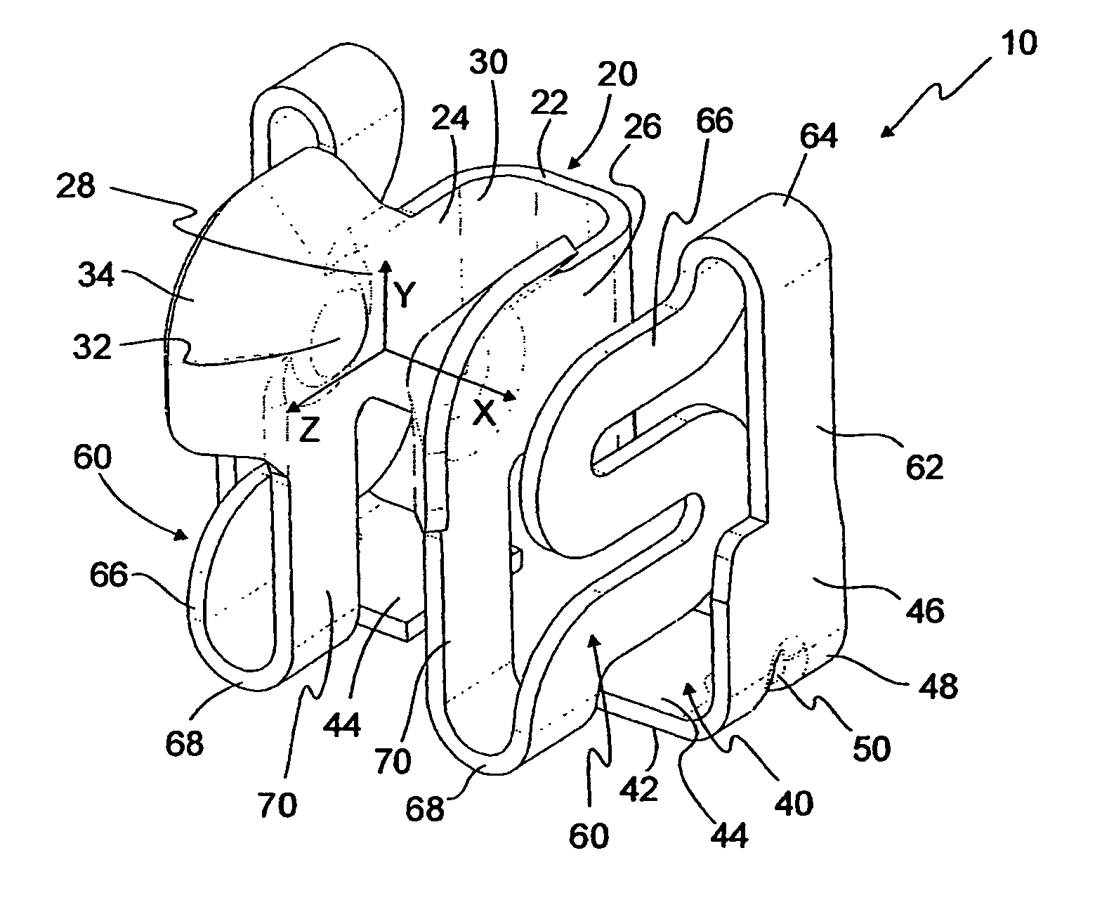
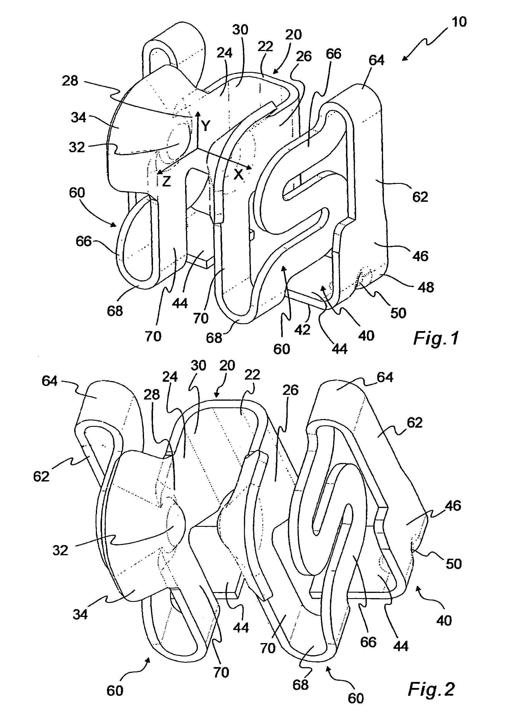
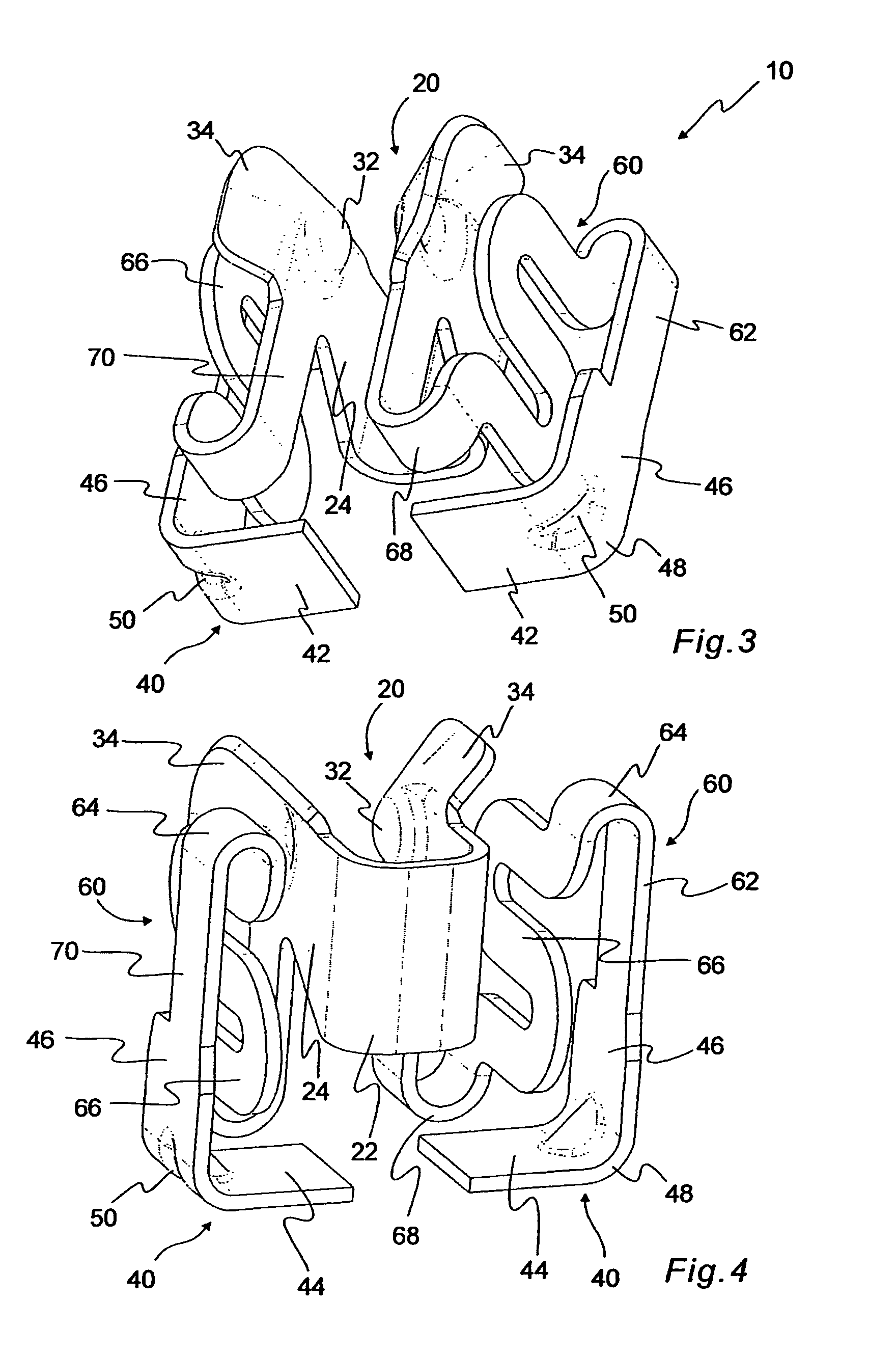
[0029]FIGS. 1–4 show a receptacle contact 10. The receptacle contact 10 includes a contact member 20, a base member 40, and spring members 60. The receptacle contact 10 is integrally formed by punching a shaped metal strip out of a metal plate and subsequently bending the metal strip. The receptacle contact 10 is substantially mirror-symmetrical with respect to the mating plane YZ, which extends perpendicular to a contact surface 42 of the base member 40.

[0030]The base member 40 comprises a bottom portion 44 and a lateral portion 46, which is upwardly bent along a bending edge 48 and arranged on a lateral outer side of the receptacle contact 10. An inwardly directed central depression 50 is provided on the bending edge 48 between the bottom portion 44 and the lateral portion 46 and reinforces the base member 40. The base member 40 may comprise a soldering surface for soldering the receptacle contact 10 to the electronic component to provide a mechanical and / or electrical connection....

second embodiment

[0044]a receptacle contact 110 is shown in FIGS. 7–9. The receptacle contact 110 includes a contact member 120, a base member 140, and spring members 160. The receptacle contact 110 is substantially mirror-symmetrical with respect to the mating plane YZ. The base member 140 comprises a bottom portion 144 with a contact surface 142 and a lateral portion 146, which is upwardly bent along a bending edge 148. Each of the spring members 160, which extend substantially parallel to the contact surface 142 in the Z-direction, is integrally attached to a back edge of the base member 140. The spring members 160 comprise a first portion 162 and a second portion 166. The first and second portions 162, 166 are strip-like in form and are arranged in separate planes that run substantially coplanar with the mating plane YZ. The first and second portions 162, 166, however, may also be inclined with respect to the mating plane YZ, as shown in FIG. 9. The first portion 162 passes into the second porti...


PUM


Abstract

A receptacle connector comprises at least one receptacle contact. The receptacle contact includes a contact member and at least one spring member. The contact member is formed for receipt of a plug contact along a mating plane. The contact member is resiliently displaceable in a direction substantial lateral to the mating plane by the spring member.

Description

FIELD OF THE INVENTION[0001]The invention relates to connectors and, more particularly, to a receptacle connector having a receptacle contact having a contact member that is resiliently displaceable in a direction substantially lateral to a mating plane.BACKGROUND OF THE INVENTION[0002]Detachable electrical connectors are used to temporarily connect electronic components or accessories with electronic devices. Besides providing a low-resistance electrical connection, the electrical connectors must be mechanically stable to ensure a permanent electrical connection. The demands on the reliability of the electrical connections are of particular importance if the electronic devices are used under conditions where mechanical stress or load occurs. For such electronic devices, rugged electrical connectors are required.[0003]A typical example of an electronic device, which may experience mechanical stress, is a mobile phone. Although specific accessories such as carrying cases are availabl...

Claims


Application Information

Patent Timeline
Patent Type & Authority Patents(United States)
IPC IPC(8): H01R4/56H01R12/71H01R24/76
CPCH01R12/57H01R13/113H01R13/14H01R13/6315H04M1/0262H01R12/727H01R12/7088
Inventor TUIN, JACOBUS NICOLAASJAEGER, PETER DIRK
Owner TYCO ELECTRONICS NETHERLAND BV
Why Eureka
Try Eureka