
Inflatable wing with manifold

a technology of manifold and wing, which is applied in the field of struts, can solve the problems of reducing the chance of significant air pressure loss, requiring effort, and losing significant air pressur

Active Publication Date: 2006-11-28
SLINGSHOT SPORTS LLC
View PDF6 Cites 14 Cited by
  • Summary
  • Abstract
  • Description
  • Claims
  • Application Information

AI Technical Summary

Benefits of technology

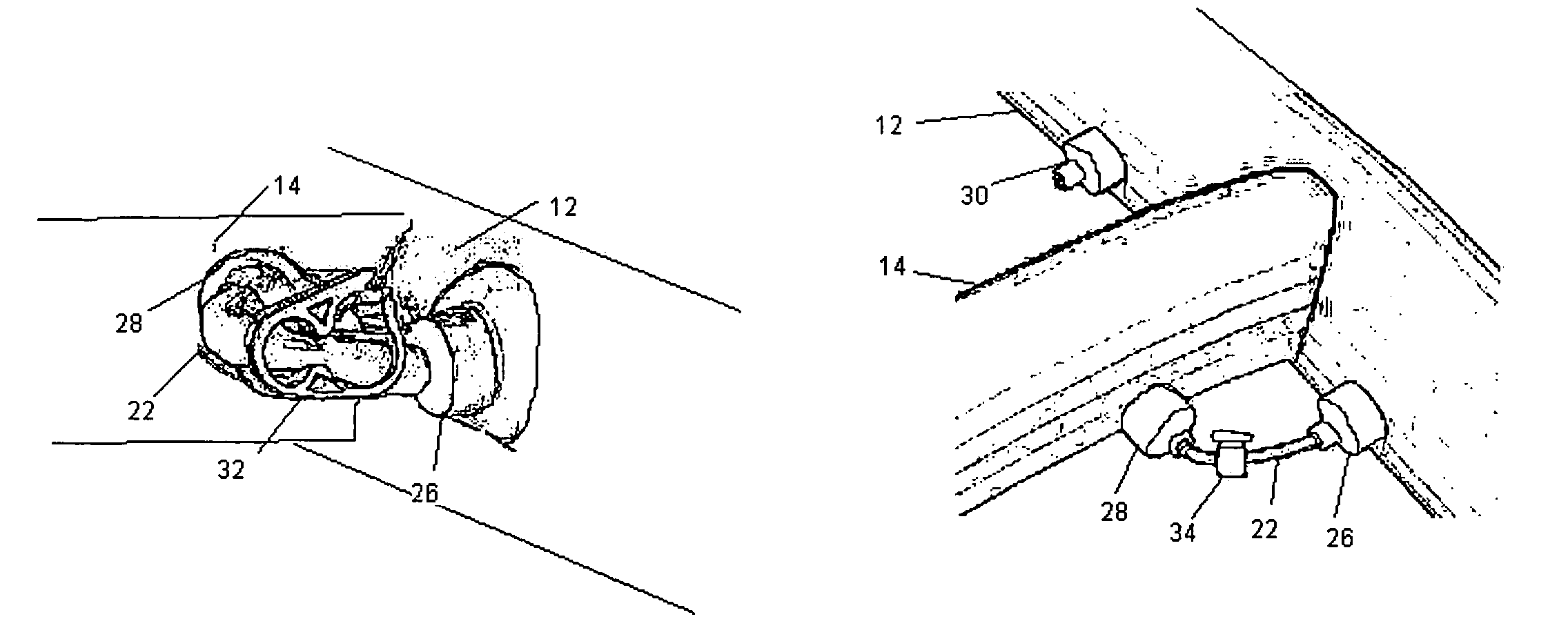
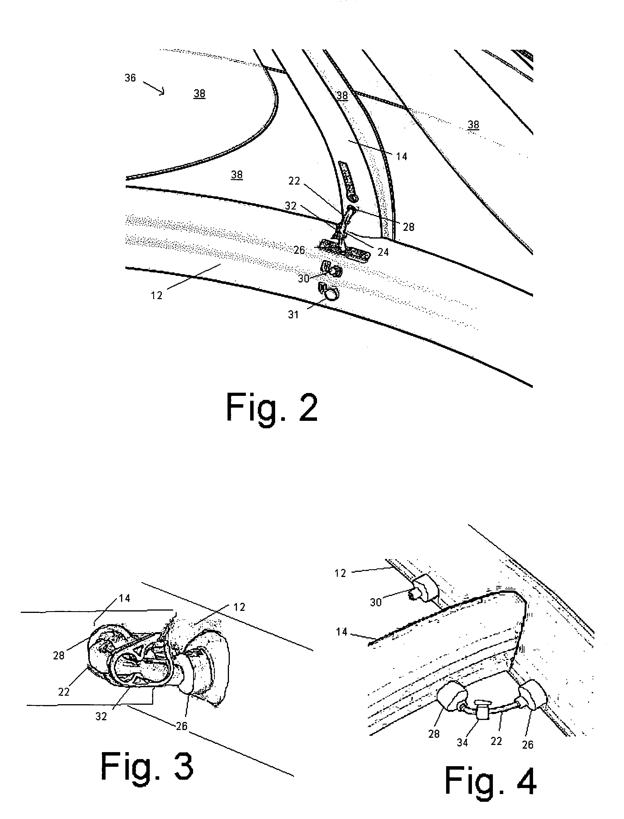
[0013]The invention is an inflatable structure comprising a plurality of inflatable chambers and a flexible material secured to the chambers wherein a primary inflatable chamber communicates by way of air pathway connections to at least one secondary inflatable chamber. In one embodiment, the structure is configured as an aerodynamic wing capable of generating lifting force, such as a LEI kite. The air pathway connection may have a valve me

Problems solved by technology

Despite the benefits offered by the inflatable design, certain drawbacks have become apparent.
This can be challenging if a check valve is not used, because it is easy to lose significant air pressure while removing the pump nozzle and closing the valve.
Although the valve stem can be pinched to reduce air loss, this requires effort, especially under adverse conditions such as cold.
Even if the valve is equipped with a check mechanism, such as a ball stopper, the operation often allows pressure loss anyway and the check mechanism can also hinder pinching the valve stem, adding to the chance of significant air pressure loss.
Although not an great burden, manipulating the valves and fitting the pump nozzle for each strut represents a significant portion of the overall time required to prepare the kite for use or to deflate the kite for transport and storage.
Using separate valves for each strut also has the potential to undermine the performance of the kite.
Since the user must independently inflate and then remove the pump nozzle before closing the valve for each strut, there is a significant chance that the struts will not be inflated to the same pressure.
As one having skill in the art will appreciate, this can cause the performance of the kite to suffer.
If there are significant differences in inflation pressure between the rib struts, the kite will not behave in a consistent manner and will have decreased stability.

Method used


Image

  • Inflatable wing with manifold
  • Inflatable wing with manifold
  • Inflatable wing with manifold

Examples


Embodiment Construction

[0022]Before describing the present invention in detail, it is to be understood that this invention is not limited to particularly exemplified materials, methods or structures as such may, of course, vary. Thus, although a number of materials and methods similar or equivalent to those described herein can be used in the practice of the present invention, the preferred materials and methods are described herein.

[0023]It is also to be understood that the terminology used herein is for the purpose of describing particular embodiments of the invention only and is not intended to be limiting.

[0024]Unless defined otherwise, all technical and scientific terms used herein have the same meaning as commonly understood by one having ordinary skill in the art to which the invention pertains.

[0025]Further, all publications, patents and patent applications cited herein, whether supra or infra, are hereby incorporated by reference in their entirety.

[0026]Finally, as used in this specification and ...


PUM


Abstract

An aerodynamic wing with a leading edge inflatable strut and at least one inflatable rib strut, wherein the struts are provided with a connection air pathway that allows the leading edge strut to act as a manifold for the inflation of the connected rib struts. Preferably, the connection air pathway is provided with a valve mechanism for selectively isolating the connected rib strut from the leading edge strut.

Description

CROSS REFERENCE TO RELATED APPLICATIONS[0001]This application claims priority of U.S. Provisional Patent Application Ser. No. 60 / 445,471, filed Feb. 7, 2003.FIELD OF THE PRESENT INVENTION[0002]The present invention relates generally to inflatable power or traction kites having a leading edge inflatable strut and one ore more inflatable rib struts that form the framework of wing of the kite. More particularly, the invention relates to a strut interconnection system that allows the simultaneous inflation of all the struts.BACKGROUND OF THE INVENTION[0003]Recently, considerable effort is being expended to develop wings capable of generating tractive force for the purposes of powering a user on a variety of vehicles that are tethered solely by flexible lines. Such wings can generally be considered kites. The development of kites capable of generating significant force has made possible numerous recreational pursuits. For example, kite surfing or kite boarding refers to a sport involving...

Claims


Application Information

Patent Timeline
IPC IPC(8): B64D17/02B63B35/79B64C31/06
CPCB63B35/7976B64C31/06B64C2031/065
Inventor LOGOSZ, TONY
Owner SLINGSHOT SPORTS LLC
Learn More