
Forming temporary airborne images

a technology for airborne images and displays, applied in firecrackers, instruments, display means, etc., can solve the problem of high production cost of sophisticated displays

Inactive Publication Date: 2006-11-28
DEFENDTEX
View PDF22 Cites 9 Cited by
  • Summary
  • Abstract
  • Description
  • Claims
  • Application Information

AI Technical Summary

Benefits of technology

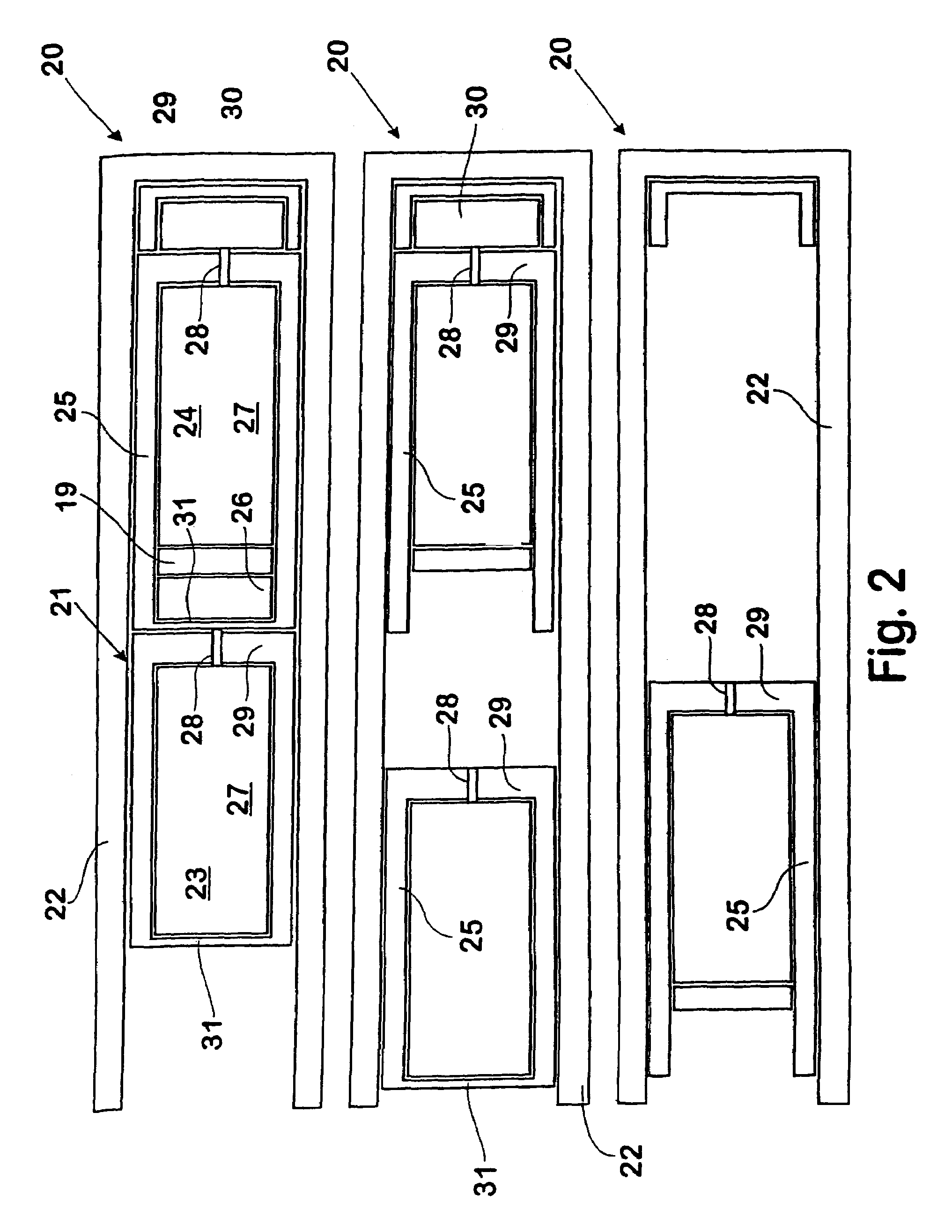
[0008]Suitably each projectile includes a trailing collar captively mounted to the projectile body and when stored in the barrel, extends rearwardly to wedge against the nose portion of a trailing projectile body. Suitably the wedging action is provided by a shallow wedge whereby, in use, the trailing end of the collar is expanded into operative sealing engagement with the barrel.
[0013]Alternatively, the image forming matter may include smoke, gas, particles or sheets or strips, such as in the nature of chaff, or other material capable of being dispersed to form, an image. The image forming matter may also include means for slowing its descent from its dispersed position, such as a parachute and the like.
[0014]The projectiles are arranged in the barrel assemblies such that once fired and the image forming matter deployed, the desired temporary airborne image is formed. Projectiles containing different image forming matter, either differing in colour or form, may be sequentially loaded into each barrel assembly.
[0015]The projectiles may be electronically fired at an infinitely variable frequency up to the maximum rate of fire. For firing from a barrel assembly according to an aspect of this invention and arranged for low pressure, low muzzle velocity, the rate of firing is limited by the time taken for each projectile to leave the barrel and by the time necessary for the gas pressure in the barrel to drop sufficiently to enable the firing of the next projectile.
[0016]The predetermined number of the plurality of projectiles may be fired from selected barrel assemblies at a rate selected to obtain the desired temporary airborne image. The firing of the projectiles may preferably be controlled by a microprocessor to permit the accurate firing of the projectiles at the selected rate.

Problems solved by technology

Generally sophisticated displays are very expensive to produce.

Method used


Image

  • Forming temporary airborne images
  • Forming temporary airborne images
  • Forming temporary airborne images

Examples


Embodiment Construction

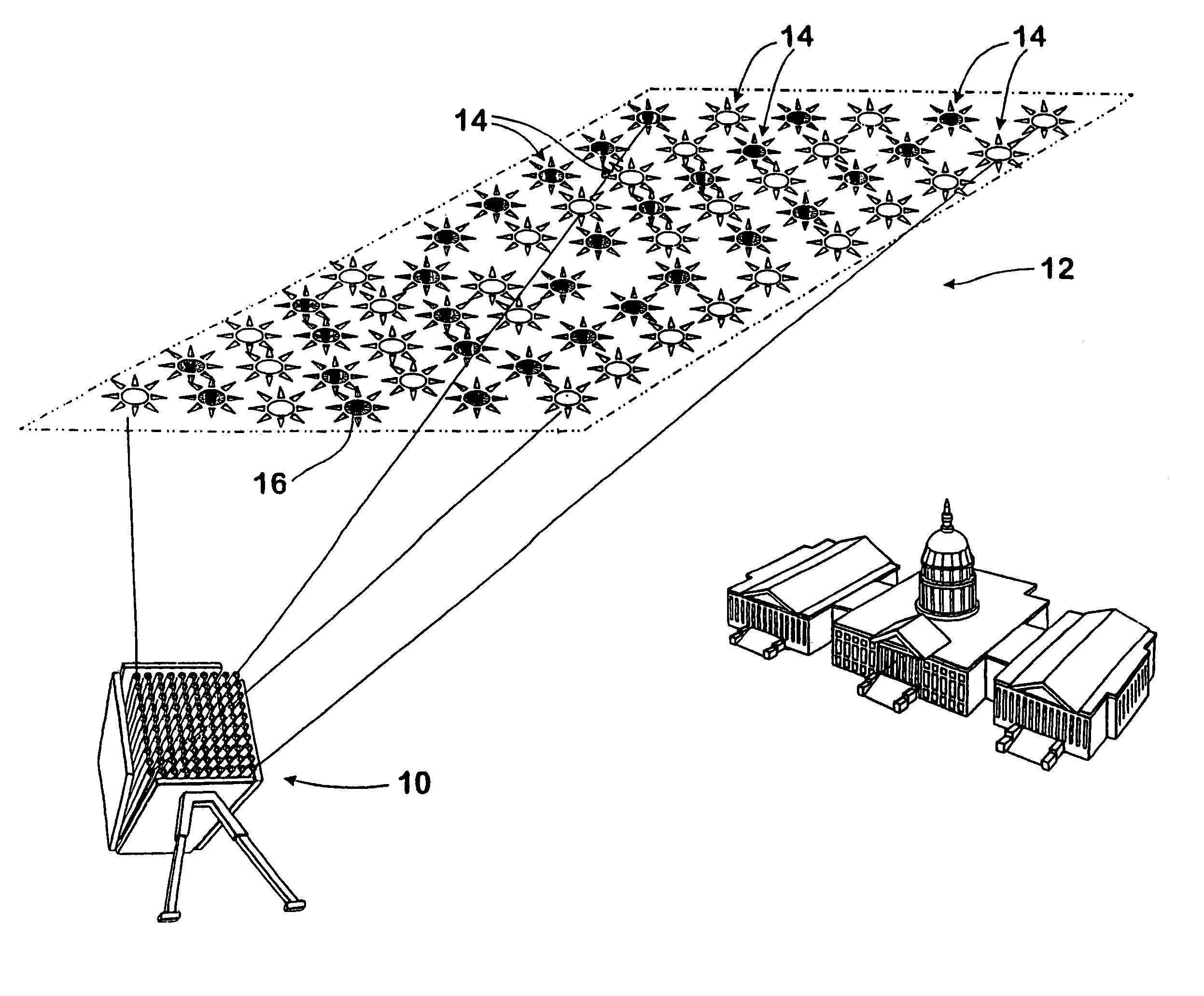
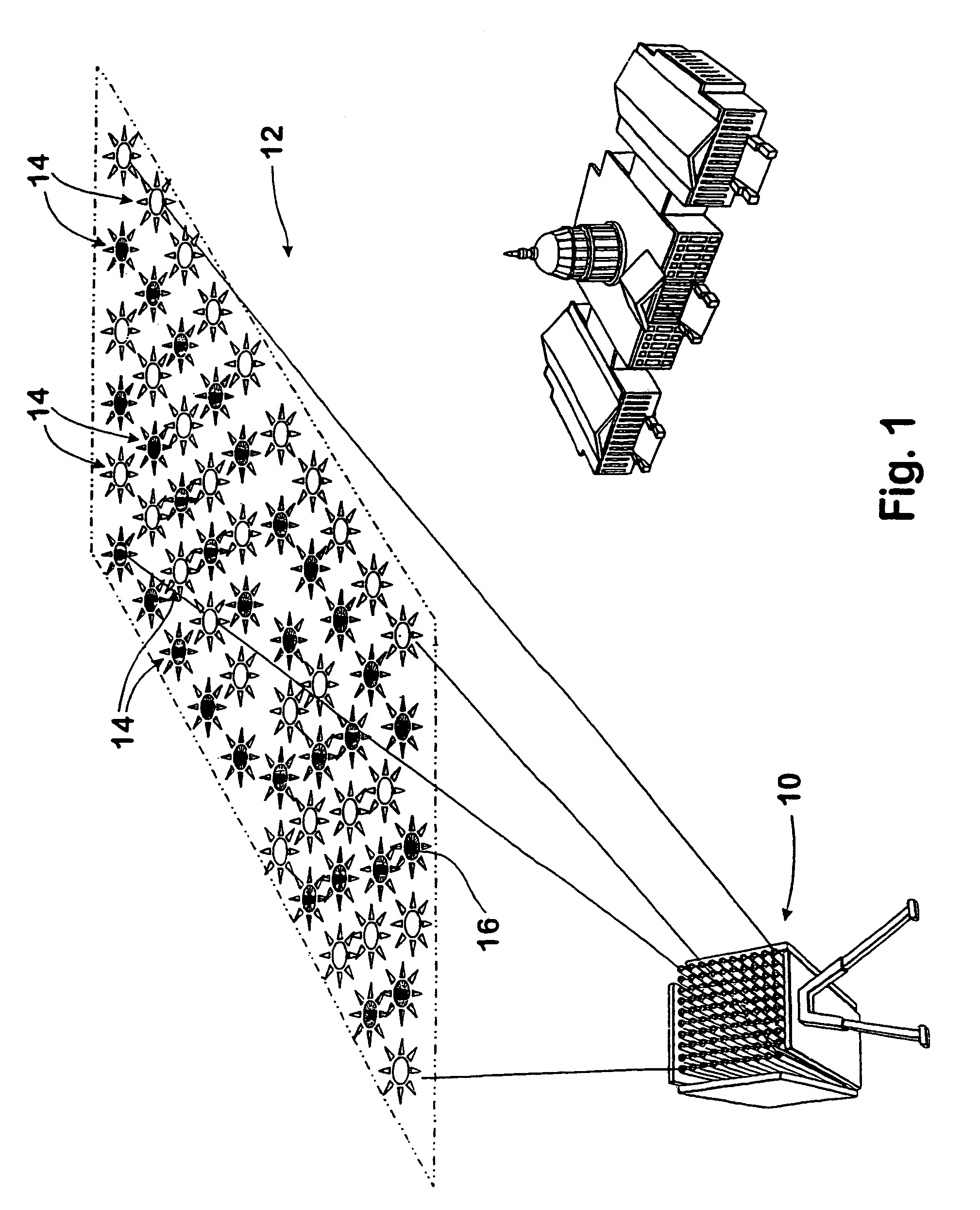
[0030]Referring to FIG. 1 of the drawings it will be seen that a group of barrel assemblies 10 of the type described loaded with mortar-like projectiles which explode mid air at a set distance and trajectory from the barrel assemblies will provide a thermal image of a selected or random configuration. The formed image 12 in FIG. 1 is fired from the barrel assemblies 10 and includes alternate clusters of respective colours at 14 which simulate or momentarily provide visible overhead stripes as well as bright burning individually discernible image portions 16 which resemble stars so that, for example, a very large flag may be momentarily printed in the sky above a festive area. The print may be formed progressively from one point or it may be formed complete in an instant.

[0031]The barrel assemblies from which the projectiles are fired may be supported on the ground or they may be supported on a watercraft or aircraft. The barrel assemblies can be controlled for selective discharge of...


PUM


Abstract

A temporary airborne image is formed by the steps of arranging a plurality of projectiles in each of one or more barrel assemblies wherein the projectiles include image forming matter; firing a predetermined number of the plurality of projectiles from selected barrel assemblies; and deploying the image forming matter to form a temporary airborne image.

Description

BACKGROUND OF THE INVENTION[0001]1. Field of the Invention[0002]The present invention relates to forming temporary airborne images. In particular, this invention relates to a method of forming temporary airborne images such as for entertainment purposes or advertising purposes.[0003]2. Description of the Related Art[0004]Temporary airborne images have been formed using pyrotechnic displays for entertainment purposes and have become very popular at national and international events with organisations spending large sums of money in order to provide new and / or interesting visual displays. In order to provide individuality, such displays are generally custom made or designed to achieve a desired display. Generally sophisticated displays are very expensive to produce.SUMMARY OF THE INVENTION[0005]We have now found a method of forming a temporary airborne image that permits the formation of a selected recognisable image. Accordingly the present invention provides a method of forming a te...

Claims


Application Information

Patent Timeline
IPC IPC(8): F42B4/04F41H11/02F42B4/24F42B5/03F42B5/15G09F13/46
CPCF41H11/02F42B5/035F42B5/15G09F13/46F42B4/24
Inventor O'DWYER, JAMES MICHAEL
Owner DEFENDTEX
Learn More