
On-machine vision detecting method of rotating cutting tool and detecting device thereof

A technology of rotary tool and detection device, which is applied in the direction of measuring device, wear resistance test, instrument, etc., can solve the problems of rotary tool rotation angle confirmation, increased time cost, and difficulty in on-machine detection, so as to save the time used for detection, The effect of improving processing efficiency and reducing installation and removal time

Active Publication Date: 2019-01-11
XIAMEN UNIV OF TECH
View PDF12 Cites 18 Cited by
  • Summary
  • Abstract
  • Description
  • Claims
  • Application Information

AI Technical Summary

Problems solved by technology

Although this detection technology can realize the wear detection of the end of the tool and the side edge, the detection of the two is independent of each other.
Therefore, for rotary tools, this detection method also needs to take multiple images and process them separately, resulting in long processing time and low processing efficiency
[0008] In addition, since the spindle of the processing machine (such as a milling machine) that rotates the tool cannot confirm the rotation angle with high precision, it is difficult to realize on-machine detection. The tool must be removed from the machine tool and installed on a special detection mechanism
If the tool wear is still within the use range, the tool needs to be installed back on the machine tool for processing, which increases the time cost

Method used


Image

  • On-machine vision detecting method of rotating cutting tool and detecting device thereof
  • On-machine vision detecting method of rotating cutting tool and detecting device thereof
  • On-machine vision detecting method of rotating cutting tool and detecting device thereof

Examples


Embodiment Construction

[0040] The present invention will be further described in detail below in conjunction with the accompanying drawings and specific embodiments. It should be noted here that the technical features involved in the various embodiments of the present invention described below can be combined with each other as long as they do not constitute conflicts with each other.

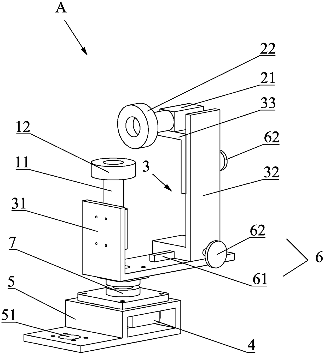
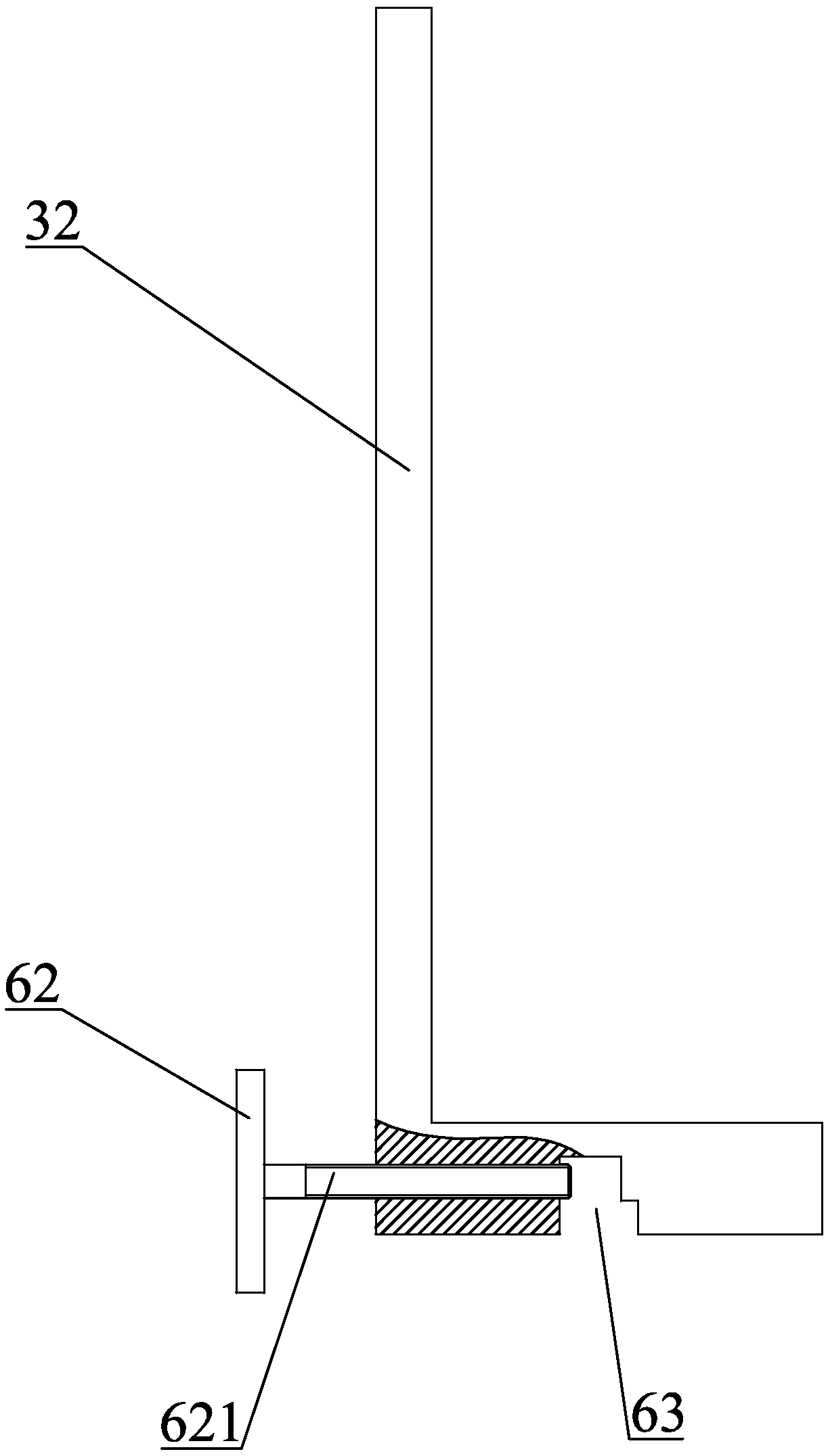
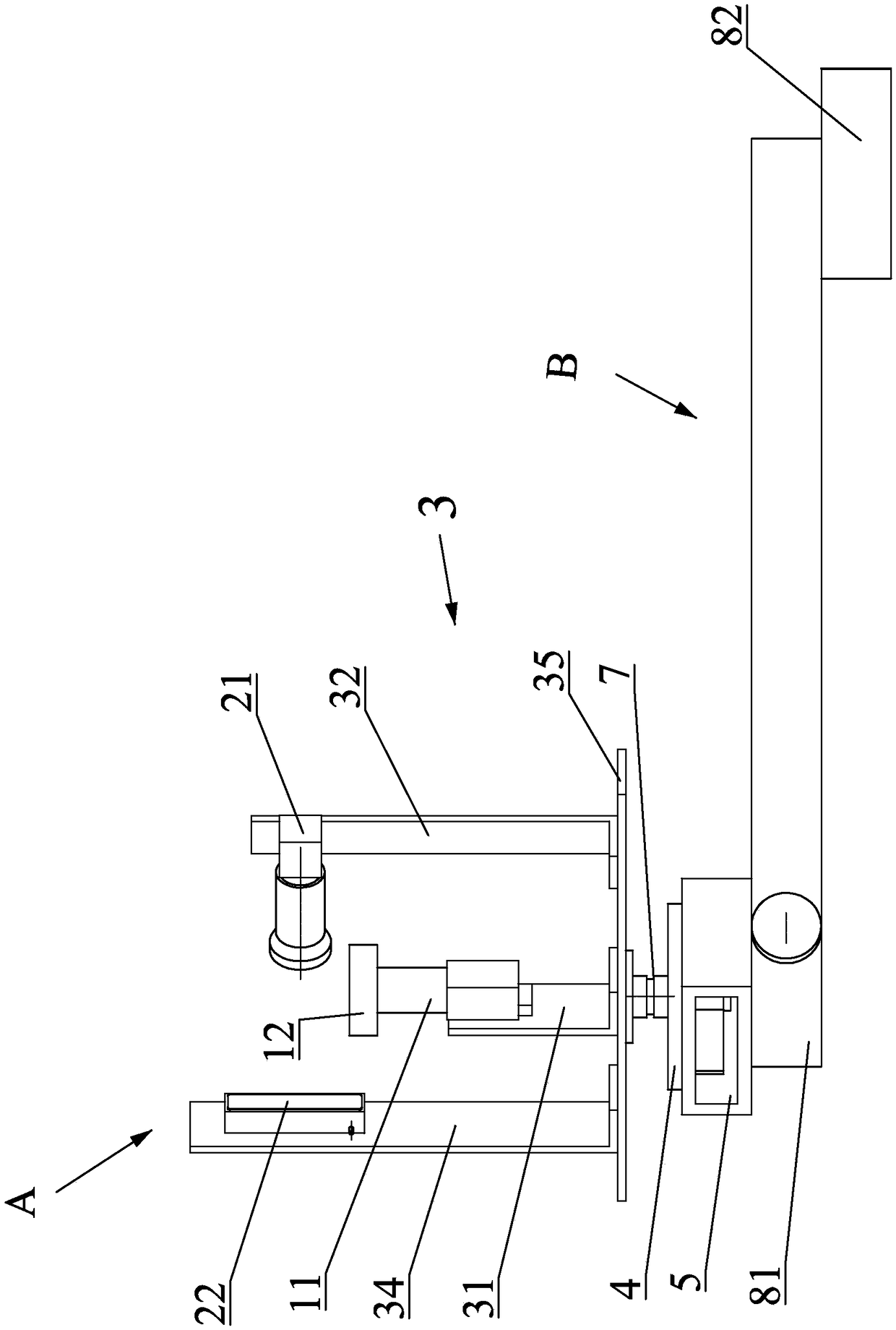
[0041] What the present invention discloses is an on-machine vision detection method of a rotary tool, such as Figure 8 Shown is a flowchart of the detection method of the present invention. The detection method is as follows: the end face of the rotary tool that is still installed on the machine tool spindle after processing is photographed by the first camera to obtain the image of the front face of the tool; the image of the front face of the tool is processed to analyze and obtain the positions of all the blades According to the position angle of each blade, control the second camera to rotate to the side edge ...


PUM


Abstract

The invention discloses an on-machine vision detecting method of a rotating cutting tool and a detecting device thereof. The method comprises the following steps that a first camera is used for capturingan image of the front cutting face of the rotary cutting tool; the image is subjected to processing and analyzing to obtain position angles of cutting edges; a second camera is controlled to rotateto the lateral cutting face according to the angels and the axis of the second camera is vertical to the lateral cutting face, and then shooting is conducted; images of the lateral cutting faces of the cutting edges are obtained; the images of the front cutting face and the lateral cutting faces are subjected to vision analyzing to obtain the abrasion condition of the cutting tool. The detectingdevice comprises the first camera and the second camera perpendicular to each other and mounted at a bracket, and further comprises a rotating motor driving the bracket to rotate. A rotating shaft ofthe rotating motor is concentric with the axis of the first camera. On-machine detection can be achieved. Abrasion areas of the lateral faces of the cutting tool can be accurately shot, and detectingefficiency is improved.

Description

technical field [0001] The invention relates to a tool wear detection device and a detection method, in particular to a visual detection method and a detection device which are applied to a rotary tool and can be detected on the machine. Background technique [0002] In automated production, an extremely critical technology is tool condition monitoring technology, which is one of the main means to reduce manufacturing costs, reduce manufacturing environmental hazards, and ensure the normal and efficient operation of the manufacturing system and product quality. Although traditional tool life management can reduce the loss caused by tool wear and breakage to a certain extent, due to the randomness of tool life, the life limit estimation is often too conservative, so that most tools are not fully utilized. Therefore, in the machining process, it is very important to regularly grasp the state of the tool, monitor and diagnose damage faults such as tool wear, to prolong the trou...

Claims


Application Information

Patent Timeline
Patent Type & Authority Applications(China)
IPC IPC(8): G01N3/56
CPCG01N3/56G01N2203/0647
Inventor 刘建春江骏杰柯晓龙黄海滨林晓辉
Owner XIAMEN UNIV OF TECH
Learn More