
Steering column lock apparatus and method

a technology for steering column locks and locks, applied in the direction of mechanical control devices, instruments, anti-theft devices, etc., can solve the problems of retraction problems, greater problems in newer steering column locks, and the need to retract the lock bol

Inactive Publication Date: 2006-11-28
STRATTEC SECURITY
View PDF121 Cites 108 Cited by
  • Summary
  • Abstract
  • Description
  • Claims
  • Application Information

AI Technical Summary

Problems solved by technology

A familiar problem with many conventional steering column locks is the ability of the lock bolt to be retracted from its locked position while torque is exerted upon the steering column.
Such a force can bind the lock bolt to prevent or resist retraction of the lock bolt from its locked position, and can present retraction problems regardless of whether the lock bolt is retracted by mechanical force from turning a key or by an actuator driving the lock bolt as described above.
While lock bolt binding is not necessarily a critical design flaw in conventional manually-actuated steering column locks, it can present greater problems in newer steering column locks that are not mechanically connected to an ignition lock cylinder for actuation thereby.
However, without the ability of a user to mechanically manipulate the lock bolt as in most older steering column lock designs described above, reliable lock bolt disengagement can be a significant problem, particularly when the lock bolt is subjected to binding forces.

Method used


Image

  • Steering column lock apparatus and method
  • Steering column lock apparatus and method
  • Steering column lock apparatus and method

Examples


Embodiment Construction

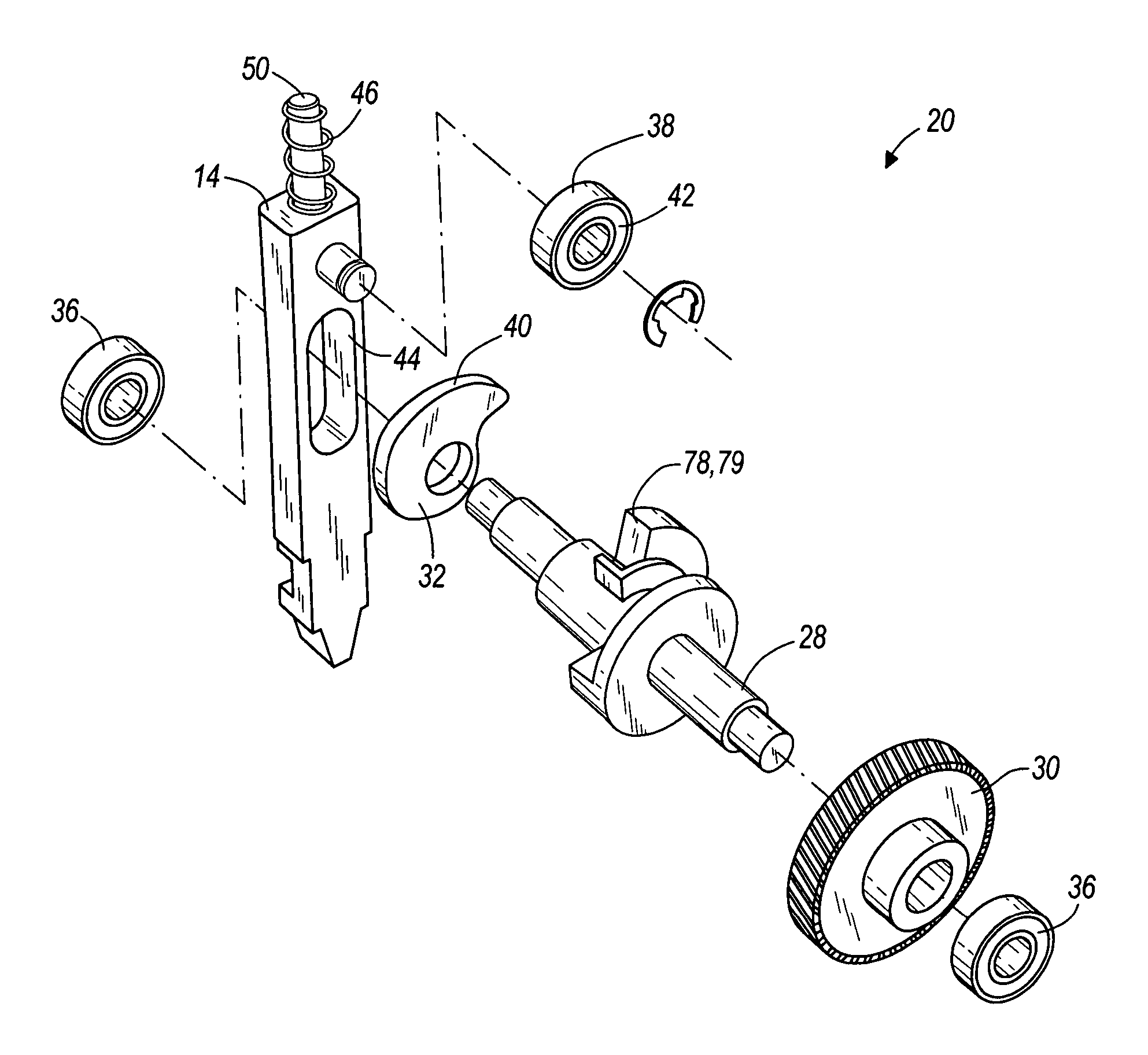
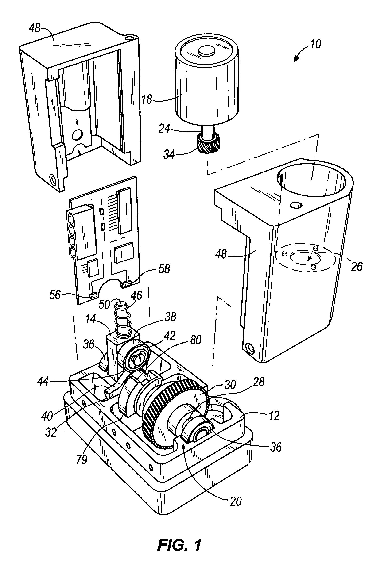
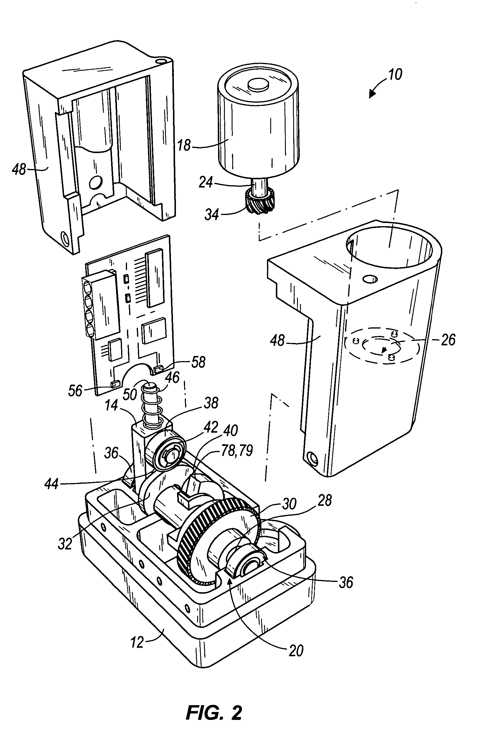
[0035]With reference first to FIGS. 1–3 which show an exemplary embodiment of the present invention, the lock apparatus 10 can have a frame 12 within which is received a lock bolt 14 that can be extended and retracted to lock and unlock a steering column (not shown), respectively. When extended, the lock bolt 14 can engage within teeth of a gear (also not shown) mounted on the steering column in a manner well known to those skilled in the art, thereby preventing the steering column from being rotated by a user or otherwise disabling or substantially disabling the steering column from use. Alternatively, the lock bolt 14 can extend into engagement within a groove, slot, recess, or other aperture in any element connected to the steering column or in the steering column itself. Like the lock bolt engagement with the gear teeth just described, the engaged lock bolt in such alternative embodiments operates to prevent steering column rotation.

[0036]The lock apparatus 10 can be mounted adj...


PUM


Abstract

A lock bolt extendible and retractable by movement of a power transmission assembly driven by an actuator and having a cam thereon which cams against the lock bolt to retract the lock bolt and unlock the steering column. In some embodiments, the cam has a curved surface with varying distance from the axis of rotation of the cam or pivot to improved lock bolt motion. The cam can have a gradual ramp surface to extract a lock bolt even in binding conditions of the lock bolt.

Description

BACKGROUND OF THE INVENTION[0001]Numerous devices and methods exist for locking a vehicle steering column from movement or for otherwise rendering the steering structure of a vehicle unusable. Most commonly, such devices and methods prevent the steering column from being rotated to steer the vehicle. The vehicle can be a car, van, truck, motorcycle, bus, or all-terrain vehicle having a number of wheels, a boat with one or more rudders, a snowmobile with skis, any vehicle having one or more tracks, and the like. A steering column lock used in any such vehicle is typically employed to prevent vehicle theft or unauthorized use.[0002]A popular and well-known mechanism for locking a steering column is a lock bolt that is directly or indirectly releasably engagable with the steering column. Such engagement can be by removable insertion of the lock bolt into a groove, a notch, teeth, or other aperture or feature in the steering column or in a gear, plate, or other element connected to the ...

Claims


Application Information

Patent Timeline
Patent Type & Authority Patents(United States)
IPC IPC(8): B60R25/02
CPCB60R25/02153Y10T70/5956Y10T70/5664
Inventor FEUCHT, MICHAEL G.JANSSEN, DAVID C.SCHUSTER, III, WILLIAM P.
Owner STRATTEC SECURITY
Learn More