
Inkjet recording apparatus

a recording apparatus and inkjet technology, applied in the direction of printing, other printing apparatus, etc., can solve the problems of reducing the accuracy of ink depositing, increasing the viscosity or hardening of ink, etc., to prevent an increase in ink viscosity or ever hardening, effective reduction of ultraviolet ray leakage toward the recording head, and high ink depositing accuracy

Active Publication Date: 2006-11-21
KONICA MINOLTA MEDICAL & GRAPHICS INC
View PDF15 Cites 21 Cited by
  • Summary
  • Abstract
  • Description
  • Claims
  • Application Information

AI Technical Summary

Benefits of technology

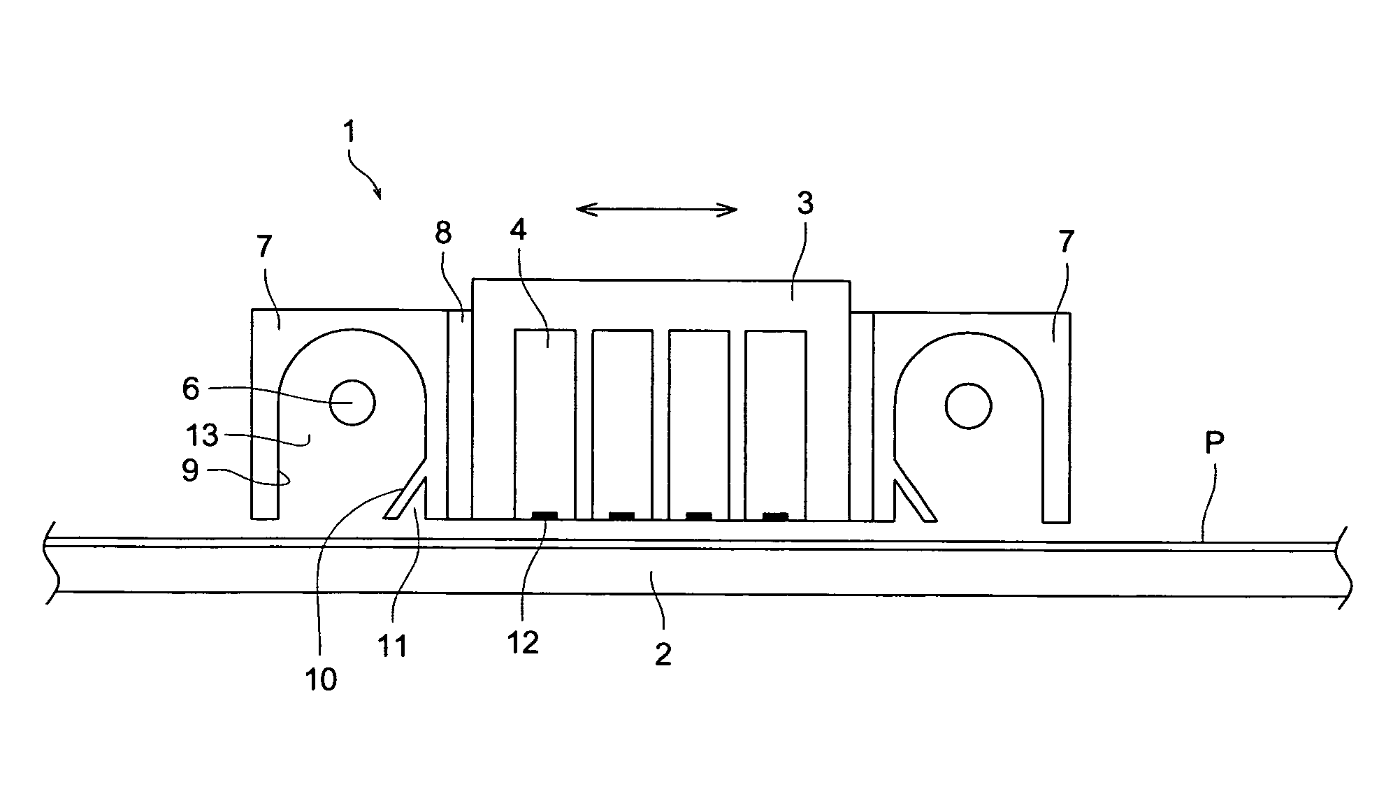
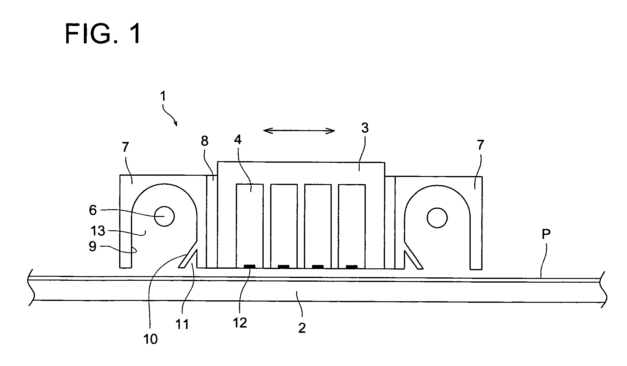
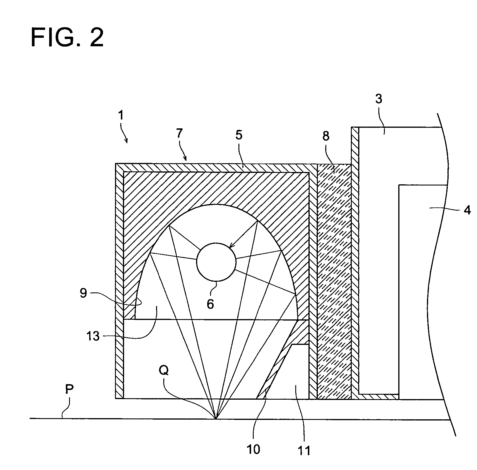
[0011]The objective of the present invention is to provide an inkjet recording apparatus, wherein the carriage or said apparatus can be downsized, and further, by reducing the amount of stray ultraviolet rays to the utmost, which are emitted from the light source, disposed adjacent to the recording head, and reach the surface (hereinafter referred to as a nozzle surface area) on which the nozzle of recording head is disposed, and thereby the ink is stably jetted over a long term, and the inkjet recording apparatus can form images having a high ink droplet depositing accuracy.

Problems solved by technology

However, when the nozzle of the recording head is as adjacent to the light source as described above, the ultraviolet rays emitted from the light source are diffusely reflected and tend to reach the nozzle, after which the ink near a nozzle mouth starts a polymeric reaction, resulting in an increase of the ink viscosity or hardened ink.
In this case, as the ultraviolet rays reach the nozzle of the recording head, any ink near the nozzle mouse causes a compound reaction, resulting in an increase viscosity or hardening of the ink, which generates the trouble of ink jetting, whereby ink depositing accuracy is decreased, and highly precise images are rarely formed, which is problematic.
In recent years, serial type inkjet recording apparatuses incorporate an ultraviolet ray emitting device on the carriage carrying the recording head, and resulting in the tendency for the carriage to become relatively large, since it incorporates various members, such as a sub-ink tank, and its downsizing is demanded.
In order to overcome the above problems, the distance between the recording head on the carriage and the ultraviolet ray emitting device has been increased, or a light trap is installed more between them, which result in a still larger size of the carriage, which does not answer downsizing.
Further in the case of a line method inkjet recording apparatus, if the distance between the recording head and the ultraviolet ray emitting device is increased, and a light trap is installed at said distance, the apparatus becomes excessively large, which of course also does not result in downsizing.

Method used


Image

  • Inkjet recording apparatus
  • Inkjet recording apparatus
  • Inkjet recording apparatus

Examples


second embodiment

[The Second Embodiment]

[0115]FIG. 4 is a schematic drawing showing the vicinity of an ultraviolet ray emitting device, featuring first reflecting section 9, being an elliptic mirror, slightly tilted with light source box 5 of ultraviolet ray emitting device 7, and second reflecting section 10. In this embodiment, distance “a” is between focal point R of ultraviolet rays reflected by first reflecting section 9 onto the recording medium P and position H of the ultraviolet ray curable ink deposited onto the recording medium, and distance “b” is between foot S which is dropped perpendicularly from light source 6 to recording medium P and position H of the ultraviolet ray curable ink deposited onto the recording medium, wherein distance “a” is greater than distance “b”. By this structure of first reflecting section 9, the concentrated light rays are diffused on recording medium P away from recording head 4, resulting in reduction of leakage of the stray ultraviolet rays toward recording ...


PUM


Abstract

An inkjet recording apparatus, including:a recording head for jetting ultraviolet ray curable ink onto a recording medium;an ultraviolet ray emitting device;a light source which emits ultraviolet rays;a first reflecting section for reflecting the ultraviolet rays; anda second reflecting section which is installed within the first reflecting section at an angle for preventing the ultraviolet rays from approaching the ultraviolet ray curable ink in the recording head, and behind the second reflecting section, a space for trapping stray ultraviolet rays diffused from the recording medium is formed.

Description

FIELD OF THE INVENTION[0001]The present invention relates to an inkjet recording apparatus, and in particular, to an inkjet recording apparatus wherein the carriage and the overall apparatus can be downsized, and wherein the amount of ultraviolet rays which reach a nozzle surface area of the recording head from a light source, disposed adjacent to the recording head, is reduced as much as possible.BACKGROUND OF THE INVENTION[0002]In recent years, as an apparatus which forms an image on a paper sheet, a resin film and fabric, by using ink, a light emission type inkjet recording apparatus is in heavy usage, wherein the ink is jetted from a nozzle of a recording head, and the deposited ink is hardened by emitted light from a light emission means, resulting in a fixed image. The inkjet recording apparatus is characterized in that it can form the image on a recording medium having the low absorbability of ink. Concerning the ink, mainly used is ultraviolet ray curable ink which is readil...

Claims


Application Information

Patent Timeline
Patent Type & Authority Patents(United States)
IPC IPC(8): B41J2/01B41J11/00
CPCB41J11/002B41J11/00214B41J11/00218
Inventor YOKOYAMA, TAKESHI
Owner KONICA MINOLTA MEDICAL & GRAPHICS INC
Learn More