
Tactile mouse

a mouse and mouse technology, applied in the field of interface devices, can solve the problems of high manufacturing cost of such devices, high cost of consumer devices, and need greater precision in their manufacture, and achieve the effects of enhancing interaction and manipulation, simple actuators, and low cos

Inactive Publication Date: 2006-11-14
IMMERSION CORPORATION
View PDF303 Cites 135 Cited by
  • Summary
  • Abstract
  • Description
  • Claims
  • Application Information

AI Technical Summary

Benefits of technology

[0008]The present invention is directed to a low-cost tactile feedback mouse device connected to a computer system, the mouse device having a simple actuator for low cost force feedback for enhancing interactions and manipulations in a displayed graphical environment.
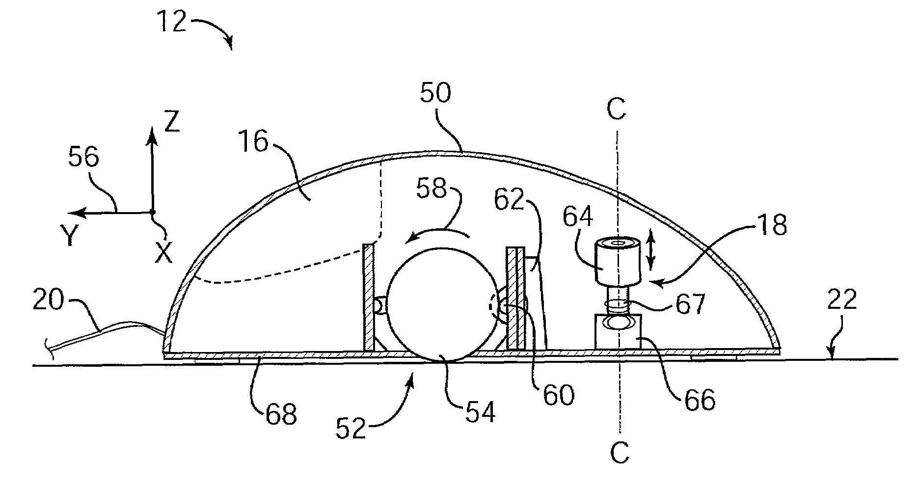
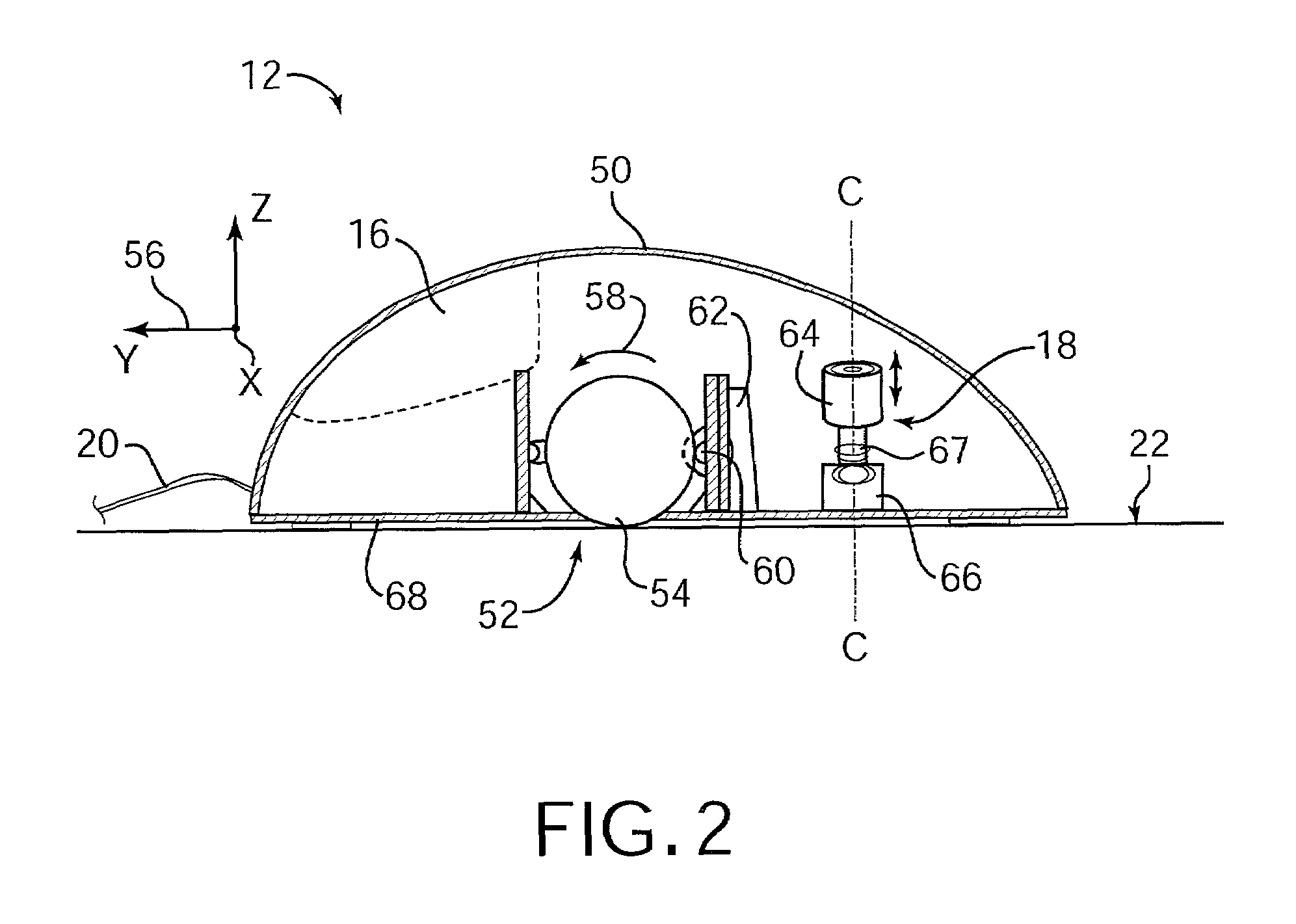
[0011]The present invention advantageously provides a haptic feedback device that is significantly lower in cost than other types of haptic feedback devices and is thus quite suitable for home consumer applications. A single actuator can be provided that applies inertial force in a particular degree of freedom, such as the Z-axis perpendicular to the X-Y plane of mouse movement. This allows crisp forces to be output without interfering with the motion or control of the mouse in the X-Y plane, and also enhances the user's experience of a third dimension relative to the mouse workspace. Furthermore, the actuator of the present invention can provide a variety of different types of force sensations to enhance the user's interfacing and experience with a computer application.

Problems solved by technology

One problem with current force feedback controllers in the home consumer market is the high manufacturing cost of such devices, which makes the devices expensive for the consumer.
A large part of this manufacturing expense is due to the inclusion of multiple actuators and corresponding control electronics in the force feedback device.
These components are complex and require greater precision in their manufacture than many of the other components in an interface device, and thus further add to the cost of the device.

Method used


Image

  • Tactile mouse
  • Tactile mouse
  • Tactile mouse

Examples


Embodiment Construction

[0018]FIG. 1 is a perspective view of a haptic feedback mouse interface system 10 of the present invention capable of providing input to a host computer based on the user's manipulation of the mouse and capable of providing haptic feedback to the user of the mouse system based on events occurring in a program implemented by the host computer. Mouse system 10 includes a mouse 12 and a host computer 14. It should be noted that the term “mouse” as used herein, indicates an object generally shaped to be grasped or contacted from above and moved within a substantially planar workspace (and additional degrees of freedom if available). Typically, a mouse is a smooth or angular shaped compact unit that snugly fits under a user's hand, fingers, and / or palm, but can also be implemented as a grip, finger cradle, cylinder, sphere, planar object, etc.

[0019]Mouse 12 is an object that is preferably grasped or gripped and manipulated by a user. By “grasp,” it is meant that users may releasably enga...


PUM


Abstract

A low-cost tactile feedback mouse device for providing haptic feedback to a user for enhancing interactions and manipulations in a graphical environment provided by a computer. The mouse device includes a sensor device able to detect the movement of the mouse in the planar workspace. An actuator is coupled to the housing of the mouse and applies an inertial force in a particular degree of freedom, preferably along an axis perpendicular to the planar workspace, where the inertial force is transmitted through the housing to the user. The actuator outputs the inertial force preferably by linearly moving an inertial mass along the Z-axis. The output force is correlated with interaction of a controlled graphical object, such as a cursor, with other graphical objects in a graphical environment displayed by the host computer. The inertial force can be a pulse, vibration, texture force, or other type of force.

Description

CROSS REFERENCE TO RELATED APPLICATIONS[0001]This application is a con of Ser. No. 09 / 456,887 filed on Dec. 7, 1999 now U.S. Pat. No. 6,211,887, which is a continuation-in-part of parent patent applications:[0002]Application Ser. No. 09 / 103,281 now U.S. Pat. No. 6,088,019, filed Jun. 23, 1998 on behalf of Louis Rosenberg, entitled, “Low Cost Force Feedback Device with Actuator for Non-Primary Axis,” and[0003]Application Ser. No. 09 / 253,132, filed Feb. 18, 1999 now U.S. Pat. No. 6,243,078 on behalf of Louis Rosenberg, entitled, “Low Cost Force Feedback Pointing Device,” both assigned to the assignee of this present application, and both of which are incorporated by reference herein in their entirety.BACKGROUND OF THE INVENTION[0004]The present invention relates generally to interface devices for allowing humans to interface with computer systems, and more particularly to computer interface devices that allow the user to provide input to computer systems and allow computer systems to ...

Claims


Application Information

Patent Timeline
Patent Type & Authority Patents(United States)
IPC IPC(8): G09G5/08A63F13/06G06F3/00G06F3/01G06F3/033H04L29/08
CPCA63F13/06G06F3/016G06F3/0338G06F3/03543G06F3/03545G06F3/0362A63F2300/1037A63F2300/1062A63F2300/8017G06F2203/013G06F2203/014G06F2203/015H04L69/329A63F13/24A63F13/285G06F3/01G06F3/0354
Inventor ROSENBERG, LOUIS B.MARTIN, KENNETH M.
Owner IMMERSION CORPORATION
Learn More