
External interfaces for a 3D graphics system

a 3d graphics and external interface technology, applied in the field of interactive graphics systems, can solve the problems of complex computer graphics generation, limited computer-generated three-dimensional graphics just a few years ago, and most of us can't actually interact with the computer doing the graphics generation, so as to reduce the amount of work

Inactive Publication Date: 2006-11-14
NINTENDO CO LTD
View PDF170 Cites 19 Cited by
  • Summary
  • Abstract
  • Description
  • Claims
  • Application Information

AI Technical Summary

Benefits of technology

[0010]One approach would be to use standardized interfaces. Computer equipment manufacturers have developed a number of standardized interfaces in the past to connect with mass storage devices, modems, and other peripheral devices. Using standardized interfaces tends to simplify design efforts and achieve component compatibility and interoperability. The typical personal computer has a number of standardized interfaces so it can be modular and compatible with hardware and peripherals designed by a number of different manufacturers. Designing a new personal computer does not require redesign of all of these interfaces.
[0021]In accordance with yet another aspect of this invention, a video interface provides efficient interfacing between a graphics processor and an external video encoder. The video interface does much of the work required so as to reduce the amount of work the external encoder needs to perform. The video interface also provides a number of interesting additional features such as panning, windowing, light gun support, and color format conversion.

Problems solved by technology

Because computer graphics generation is complex, computer-generated three-dimensional graphics just a few years ago were mostly limited to expensive specialized flight simulators, high-end graphics workstations and supercomputers.
The public saw some of the images generated by these computer systems in movies and expensive television advertisements, but most of us couldn't actually interact with the computers doing the graphics generation.
A problem graphics system designers confronted in the past was how to efficiently couple system components together.
A modern 3D graphics system is relatively complex, and requires a number of different connections between different aspects of the system.
While the standardized interface approach has certain advantages in the arena of general purpose computing, it may not be suitable for home video game platforms.
Using standard interfaces may be easier from a design standpoint, but a standardized interface may not provide the high performance that a customized interface might offer.
Another issue relates to hardware interoperability.
This increases cost.
In addition, no security system is impenetrable.

Method used


Image

  • External interfaces for a 3D graphics system
  • External interfaces for a 3D graphics system
  • External interfaces for a 3D graphics system

Examples


example graphics

Pipeline

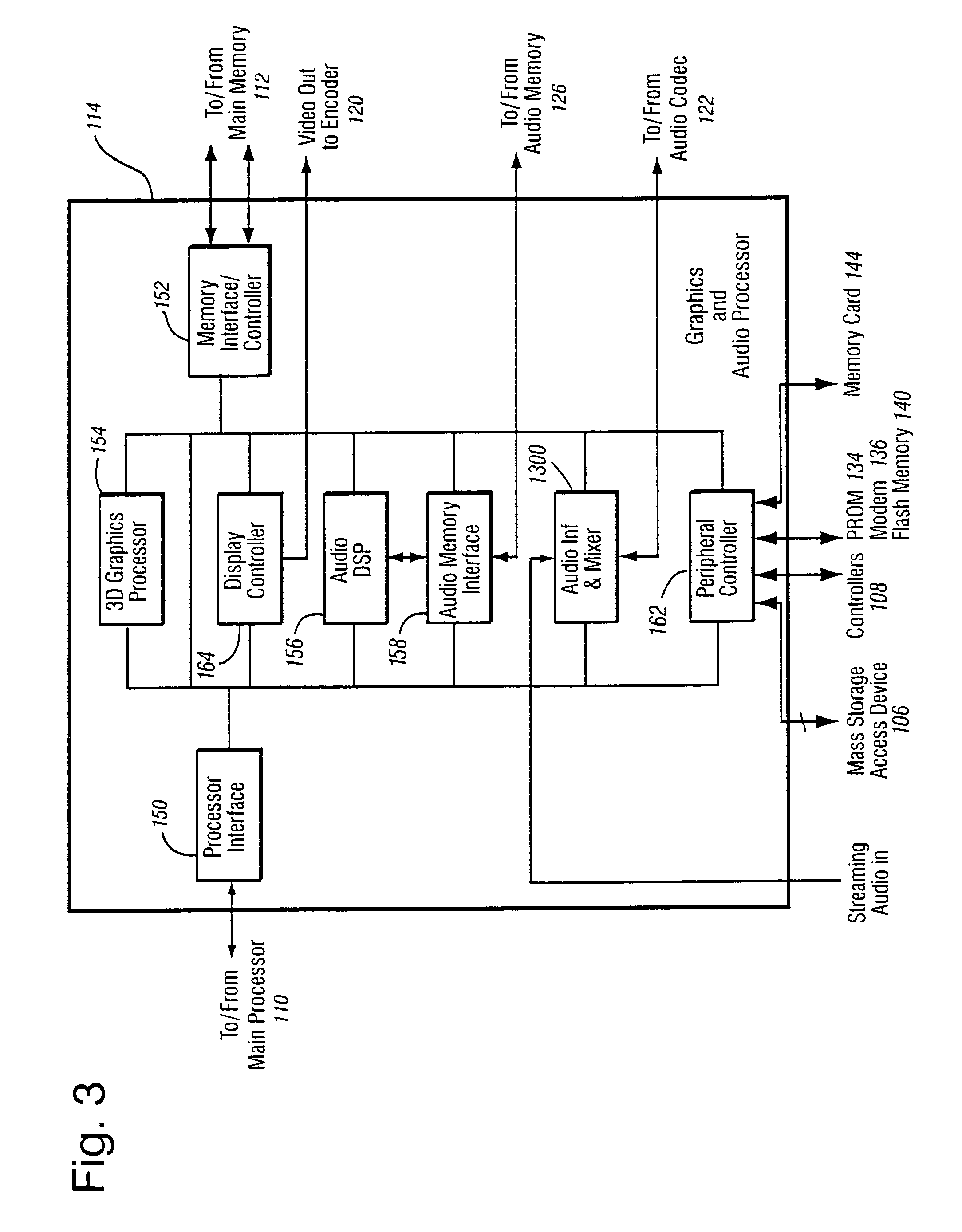
[0080]FIG. 4 shows a more detailed view of an example 3D graphics processor 154. 3D graphics processor 154 includes, among other things, a command processor 200 and a 3D graphics pipeline 180. Main processor 110 communicates streams of data (e.g., graphics command streams and display lists) to command processor 200. Main processor 110 has a two-level cache 115 to minimize memory latency, and also has a write-gathering buffer 111 for uncached data streams targeted for the graphics and audio processor 114. The write-gathering buffer 111 collects partial cache lines into full cache lines and sends the data out to the graphics and audio processor 114 one cache line at a time for maximum bus usage.

[0081]Command processor 200 receives display commands from main processor 110 and parses them—obtaining any additional data necessary to process them from shared memory 112. The command processor 200 provides a stream of vertex commands to graphics pipeline 180 for 2D and / or 3D processi...

example disk

Interface

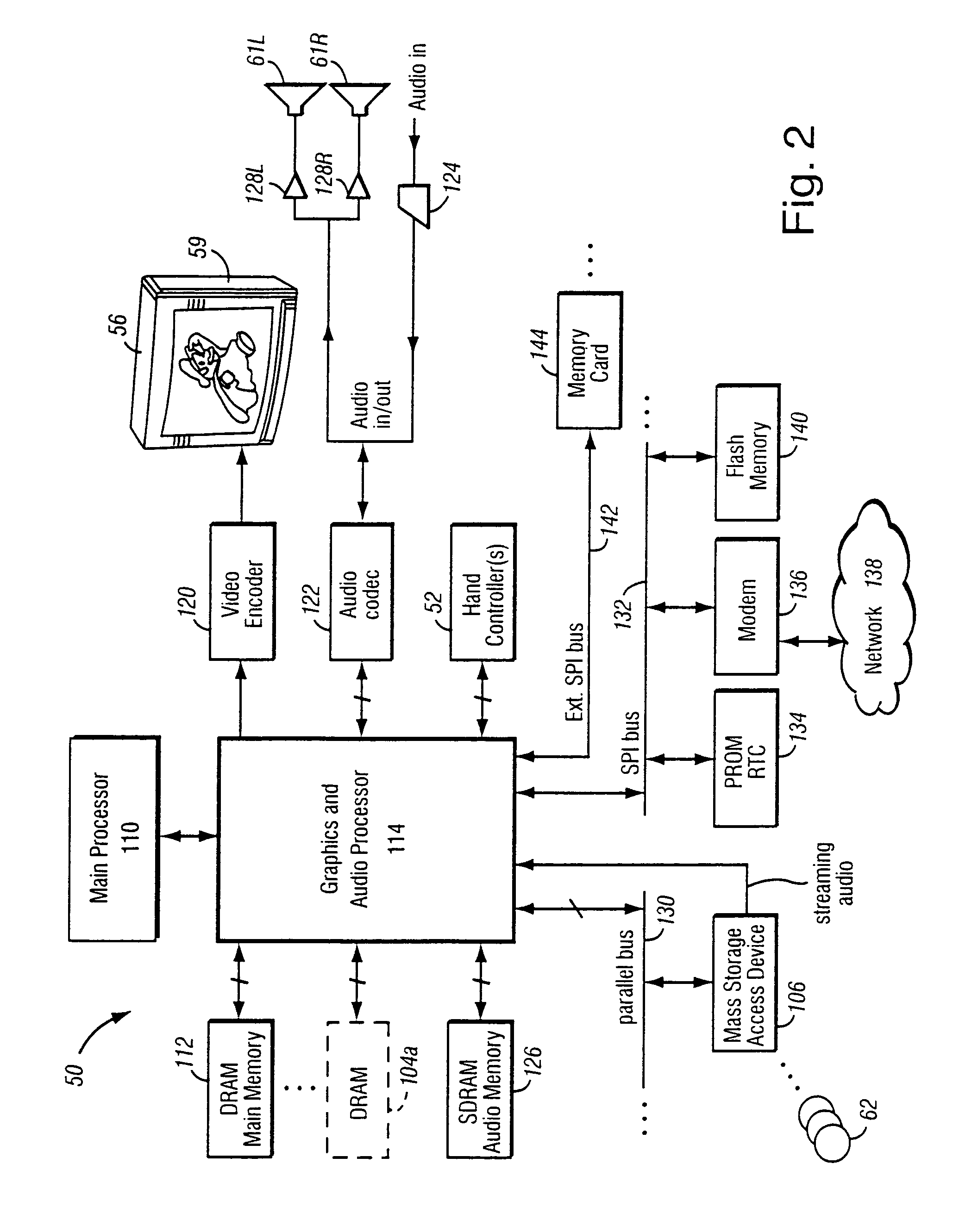
[0104]FIG. 7A shows the external interface of disk interface 1200. In the example embodiment, bus 130 to / from disk interface 1200 is connected directed to mass storage access device 106 (which in the example embodiment may comprise an optical disk drive). In the example embodiment, bus 130 is a parallel bus having a single device on it, with disk interface 1200 being the only master and the mass storage access device 106 being the only target device. Disk interface 1200 communicates with main processor 110 via a SPU interface 1202 and an interrupt line 1204, and communicates with memory controller 152 via memory controller interface 900.

[0105]FIG. 7B shows a more detailed block diagram of an example disk interface 1200. In this example, disk interface 1200 includes a CPU interface block 1206, a memory controller interface block 1208, and various buffers including a buffer 1210, a buffer 1212, a DMA FIFO 1214, a direct memory access controller 1216, and an interrupt register...

example external

Interface Connections

[0361]FIGS. 15A–15C show example external interface connections for use in coupling the example external interfaces described above in connection with FIGS. 9A–9E to external interface connectors 1516, 1518, 1520, respectively. In the example embodiment, the external interface connections for EXI0 and EXI1 are virtually identical. As shown in FIGS. 15A and 15B, the external interface buses described above in connection with FIGS. 9A, 9B and 9C are isolated with various isolation circuitry and coupled to respective pins of a multi-pin connector (1516 for the EXI0 bus, 1518 for the EXI1 bus) with pin assignments as follows:

[0362]

Pin NumberSignal Identification1EXTIN2GND3INT43.3 volts5DO65 volts7DI83.3 volts9CS10Ground11CLK12EXTOUT

[0363]FIG. 15C shows an example connection between the external interface channel 2 shown in FIG. 9D and an example 8-pin connector 1520 having the following pin assignments.

[0364]

Pin NumberSignal Identification13.3 volts2GND3INT4CLK5DO6D...


PUM


Abstract

An advantageous set of external interfaces for home video game platform provide modularity and expandability while maintaining and preserving the proprietary nature of the platform. A disk drive interface provides flexible communications with an internal disk drive. Various serial bus interfaces provide expandability and interconnectability with a variety of internal and external devices including, for example, flash memory, broadband adapters, modems, and various other devices. A 4-port game controller interface provides serial interconnectability with handheld game controllers and various other input / output device. Power supply, digital and analog audio / video connections, and parallel memory expansion connections are also provided.

Description

RELATED APPLICATIONS[0001]This application is a continuation of application Ser. No. 09 / 723,335, filed Nov. 28, 2000, now U.S. Pat. No. 6,609,977 which claims the benefit of provisional Application No. 60 / 226,884, filed Aug. 23, 2000.[0002]This application is related to the following applications identified below, each of which is hereby incorporated herein by reference:[0003]U.S. application Ser. No. 09 / 722,664 filed Nov. 28, 2000 of Shimuzu et al., entitled “Controller Interface For A Graphics System” which claims priority from provisional application No. 60 / 226,885 filed Aug. 23, 2000;[0004]U.S. application Ser. No. 09 / 723,336 filed Nov. 28, 2000 of Parikh et al. entitled “Application Program Interface for a Graphics System”, now U.S. Pat. No. 6,452,600; and[0005]Design application Serial No. 29 / 128,262 filed Jul. 31, 2000 of Ashida entitled “Video Game Machine”, now D453,800.FIELD OF THE INVENTION[0006]The present invention relates to computer graphics, and more particularly to ...

Claims


Application Information

Patent Timeline
IPC IPC(8): A63F13/02G06F13/40
CPCA63F13/02A63F13/08G06F13/385A63F2300/20A63F2300/203A63F2300/1025A63F13/23A63F13/95
Inventor SHIMIZU, DANTAKEDA, GENYOSHIOTA, KOOIRA, MUNEHITOKOSHIMA, KAZUONISHIUMI, SATOSHI
Owner NINTENDO CO LTD
Learn More