
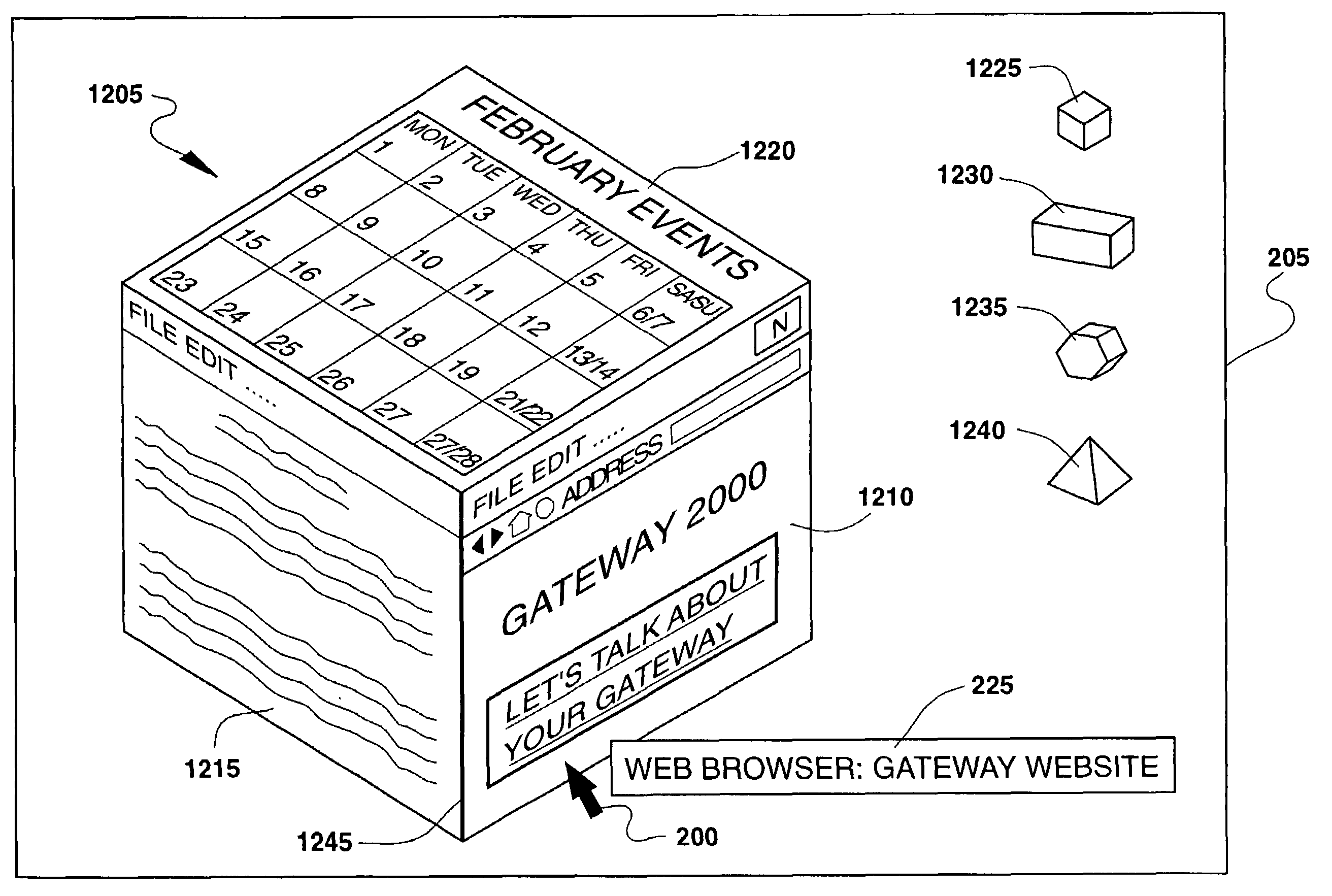
Simulated three-dimensional navigational menu system

a three-dimensional navigation and menu system technology, applied in the field of automatic option display systems, can solve the problems of increasing software complexity, unable to gain access to, or become aware of, all the options available to a user,

Inactive Publication Date: 2006-11-07
GATEWAY +1
View PDF32 Cites 269 Cited by
  • Summary
  • Abstract
  • Description
  • Claims
  • Application Information

AI Technical Summary

Benefits of technology

[0018]It is an object of the present invention to provide a more informative and useful method of identifying selectable options in a user interface.
[0026]The present invention further provides the advantage of providing this display of options to the user while still allowing the user to utilize the remainder of the display space to operate other applications.

Problems solved by technology

Today, computers are drastically more complex than the computers from a year ago.
With this growth in hardware complexity has been an equal, if not greater, growth in software complexity.
The problem with this advancement in software is that trying to gain access to, or become aware of, all the options available to a user is nearly impossible unless the user has some prior knowledge.
The problem with this method is that as these options, and their corresponding icons, grow in number, display space remains limited.
A desktop with too many icons creates a disorganized and difficult-to-decipher workspace.
However, that would limit their ability to convey their presence to a user, not to mention make them more difficult to read, move, or select.
Although this helps the user to a certain extent, there remains a problem with newer, more advanced GUI technology.
The constant motion, changing of shape, and changing of size of these selectable targets also presents a problem for the conventional methods of target highlighting mentioned above.
To configure the animated display to further change the appearance of the moving targets in the presence of a cursor would be very problematic, if not impossible.

Method used


Image

  • Simulated three-dimensional navigational menu system
  • Simulated three-dimensional navigational menu system
  • Simulated three-dimensional navigational menu system

Examples


Embodiment Construction

[0040]In the following detailed description of preferred embodiments, reference is made to the accompanying drawings that form a part hereof, and in which is shown by way of illustration, specific preferred embodiments in which the invention may be practiced. These embodiments are described in sufficient detail to enable those skilled in the art to practice the invention, and it is to be understood that other embodiments may be utilized, and that logical, mechanical and / or electrical changes may be made without departing from the spirit or scope of the invention. To avoid detail not necessary to enable those skilled in the art to practice the invention, the description may omit certain information known to those skilled in the art. The following detailed description is, therefore, not to be taken in a limiting sense, and the scope of the present invention is defined only by the appended claims.

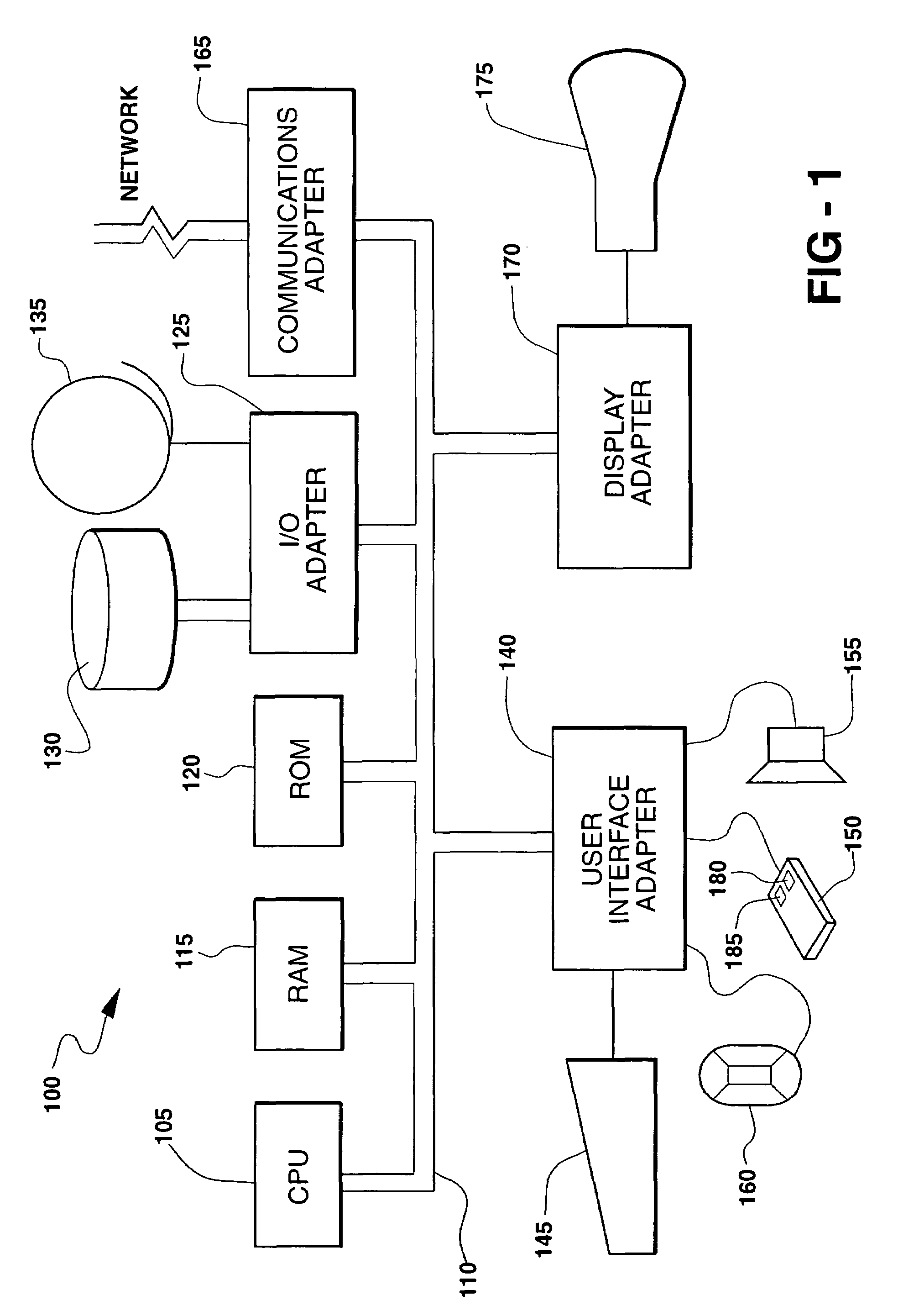
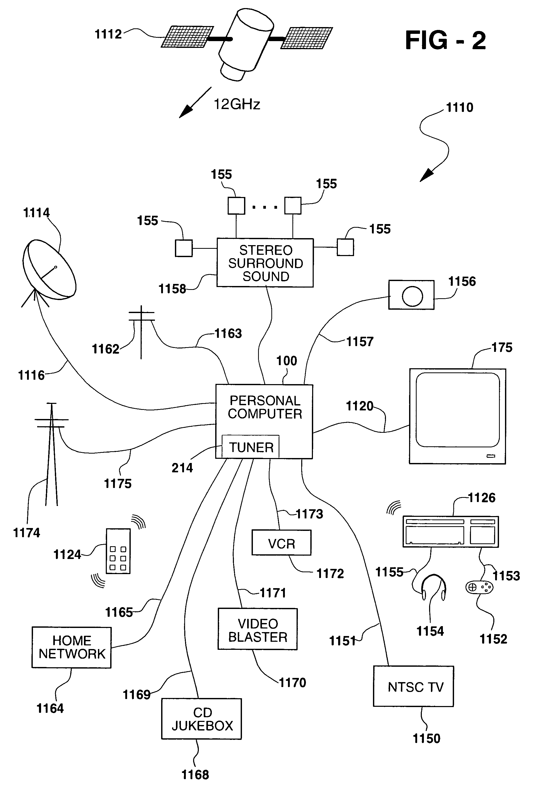
[0041]A representative hardware environment for practicing the present invention is depict...


PUM


Abstract

A user interface, system, method and software for displaying a simulated three-dimensional display of menu options to a user, thereby maximizing use of a display's real estate by presenting all available options at once while at the same time presenting certain options in a more pronounced manner. The system monitors for running applications, polls the running applications for any available options, and displays the options in the simulated three-dimensional format. With this type of dynamic menu, standard means for bringing focus to a selectable target create complexities, and are thus avoided by designing the system's cursor to duplicate the appearance of the selected target's shape, preferably in a smaller size.

Description

FIELD OF THE INVENTION[0001]This invention relates generally to option display systems and more particularly to automated option display systems.BACKGROUND OF THE INVENTION[0002]Today, computers are drastically more complex than the computers from a year ago. With this growth in hardware complexity has been an equal, if not greater, growth in software complexity. By being able to build onto previously developed applications, software designers have been able to easily increase the number of options available from any given application.[0003]The problem with this advancement in software is that trying to gain access to, or become aware of, all the options available to a user is nearly impossible unless the user has some prior knowledge. With computer display space at a premium, many software developers include these expanded features into hierarchical menus that many users, especially novice users, liken to a maze. Other software developers attempt to give the user a display of all t...

Claims


Application Information

Patent Timeline
IPC IPC(8): G06F3/00G06F3/033G06F3/0481G06F3/0482
CPCG06F3/04812G06F3/0482G06F2203/04802
Inventor SMITH, KIM C.WUGOFSKI, THEODORE DAVIDMOSTYN, MICHAELKAYL, THOMAS A.
Owner GATEWAY
Learn More