
Apparatus productivity improving system and its method

Inactive Publication Date: 2006-11-07
TOKYO ELECTRON LTD
View PDF14 Cites 43 Cited by
  • Summary
  • Abstract
  • Description
  • Claims
  • Application Information

AI Technical Summary

Benefits of technology

[0011]In consideration of the aforementioned circumstances, an object of the present invention is to provide a system and method for improving productivity of the apparatus.
[0012]Moreover, another object of the present invention is to provide a system and method that is capable of performing efficient maintenance management of the apparatus.

Problems solved by technology

In recent years, the life cycle of industrial products, particularly electronic devices become extremely short due to more intensification in development competition between manufactures.
Moreover, since the production is uniquely placed in the apparatus, there is a possibility that the method for transmitting a large amount of data including other data excepting one for remote-maintenance to the vendor via the host computer will decrease the throughput of the apparatus, and this is not realistic.
However, even in when the preventive maintenance is performed, it is necessary to stop the apparatus, and the frequent or inefficient preventive maintenance reduces the substantial operation rate of the apparatus and suppresses productivity.

Method used


Image

  • Apparatus productivity improving system and its method
  • Apparatus productivity improving system and its method
  • Apparatus productivity improving system and its method

Examples


Embodiment Construction

[0055]The following will explain the apparatus productivity improvement system and its method according to the present embodiment. The present embodiment explains, as an example, a case in which a vendor is a manufacturer for a semiconductor manufacturing apparatus and a manufacturer is a semiconductor device manufacturer.

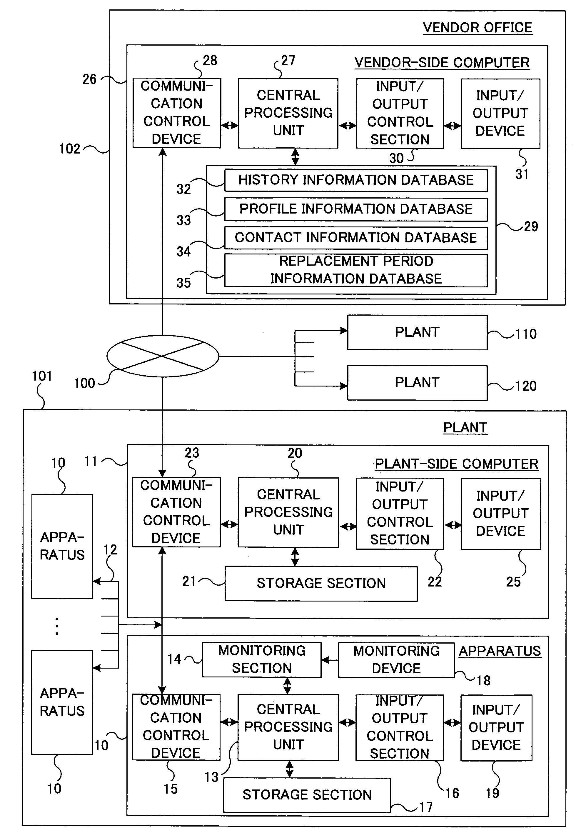
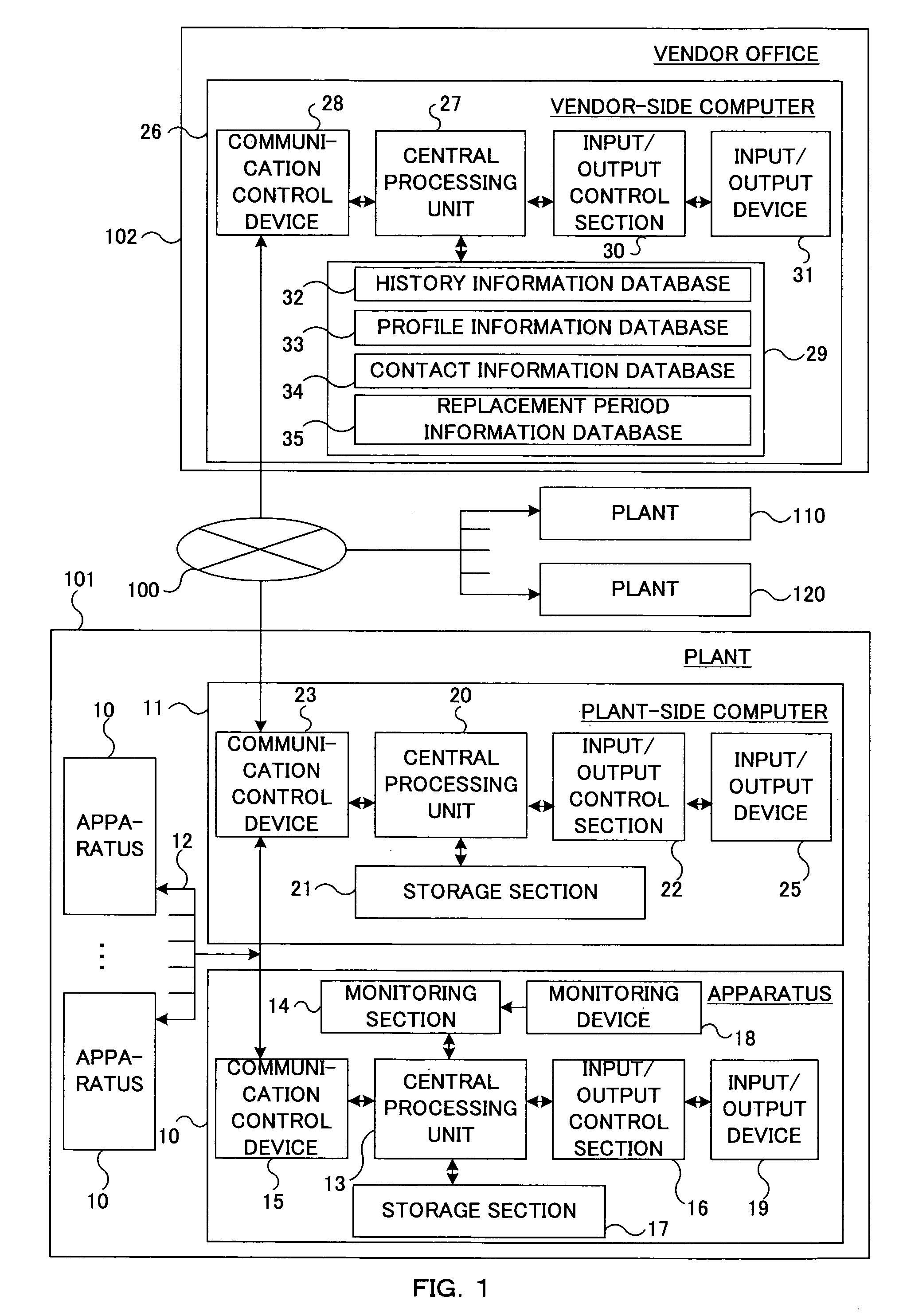
[0056]FIG. 1 is a structural view of a system according to an embodiment of the present invention.

[0057]As illustrated in FIG. 1, the system of the present embodiment is composed of a plant 101 where apparatuses 10 that are supplied by a vendor is used, a vendor's office 102, which is placed at a remote site from the plant 101, and a communication line 100 that connects the plant 101 and the vendor's office 102.

[0058]The plant 101 is, for example, a semiconductor manufacturing plant and includes, in its interior, apparatuses 10, a plant-side computer 11, and a plant internal wiring network that connects each apparatus 10 and the plant-side computer 11.

[0059]The app...


PUM


Abstract

There is provided a system and method for monitoring an apparatus from a remote location. A vendor-side computer obtains operating state data obtained by a monitoring device provided in an apparatus via a communication line, and monitors the operating state of the apparatus from a remote location. Maintenance data at a part replacing time is transmitted from the apparatus, and the vendor-side computer that has received maintenance data calculates an optimal replacement period of a part based on this. The calculated optimal replacement period of each part is sent to a plant. The plant feeds the optimal replacement period back to the operation of the apparatus, so that productivity can be improved.

Description

[0001]This application is a National Phase Application filed under 35 U.S.C. § 371 and based on PCT / JP02 / 00427, filed Jan. 22, 2002, the content of which is incorporated herein by reference, and claims the priority of Japanese Patent Application No. 2001-013571, filed Jan. 22, 2001.TECHNICAL FIELD[0002]The present invention relates to an apparatus productivity improving system and its method, and for example, an apparatus productivity improving system and its method that makes apparatuses for productivity such as electronic devices and the like remote-controllable to improve an operation rate of the apparatus and obtain improvement in productivity.BACKGROUND ART[0003]In recent years, the life cycle of industrial products, particularly electronic devices become extremely short due to more intensification in development competition between manufactures. Under such circumstances, the manufactures for the electronic device manufacturing apparatus are required to provide the manufacturin...

Claims


Application Information

Patent Timeline
IPC IPC(8): G06F17/00G05B23/02
CPCG05B23/0283G05B2219/32233Y02P90/80G06Q50/00
Inventor KARASAWA, WATARU
Owner TOKYO ELECTRON LTD
Learn More