
Tape drive apparatus with a head alignment system

a tape drive and head alignment technology, applied in the field of tape drives, can solve the problems of repeated alignment setting operations, increased alignment time, and increased alignment time, and achieve the effect of reducing the number of alignments

Inactive Publication Date: 2006-11-07
QUANTUM CORP
View PDF8 Cites 9 Cited by
  • Summary
  • Abstract
  • Description
  • Claims
  • Application Information

AI Technical Summary

Benefits of technology

[0010]There is a need for a head-alignment system and process to align a magnetic recording head within a tape drive apparatus within the required limits, and have this setting be considered a final step of the procedure. Furthermore, a process and apparatus are needed to provide resistance against any reasonable shock and vibration. At the same time, it is desirable to provide for an accessible alignment mechanism that allows convenient access to reset the alignment without substantial disassembly or damage to the tape drive. Furthermore, a predictable and precise process and apparatus are needed to align the system with the fine resolution needs of modern high-capacity tape drives. There is also a need for a system that does not interface with any functional components of the tape drive or affect the performance of any tape drive components due to the setting requirement.

Problems solved by technology

However, although this should be considered a final step of the procedure, conventional practices have often required additional steps to lock the alignment into place.
A concern with this is that the locking operation itself often causes the alignment to change and require repetition of the alignment setting operation.
Another problem present in conventional systems is the potential migration of the head or the head positioning system when the tape drive is subjected to a reasonable shock or vibration.
When this occurs, the head alignment changes and affects the write-read performance of the tape drive.
Conventional systems strictly rely on fasteners to keep the alignment in place and do not provide adequate protection to secure the alignments against a shock-vibration environment.
Conventional systems use cams, for example, to set such alignments, but do not provide for the calibration of the cam rotation to correct certain skew amounts nor provide a mechanism for rotating these cams.
Another concern with the head alignment systems is the difficulty in re-setting alignments in conventional tape drives without incurring either a large amount of disassembly or without damaging the tape drive.
If for any reason the alignment is not within the required specifications, the bond joint must be broken and in turn, the head may get damaged.
In addition, application of the bonding agent near the head element is not a preferred procedure, as the adhesive may get deposited on the head surface and result in deterioration of write-read processes.
Certain conventional alignment processes will affect the performance of certain critical components of the tape drive.
This can result in the reduction in the life of these components or hinder the performance of the system.

Method used


Image

  • Tape drive apparatus with a head alignment system
  • Tape drive apparatus with a head alignment system
  • Tape drive apparatus with a head alignment system

Examples


Embodiment Construction

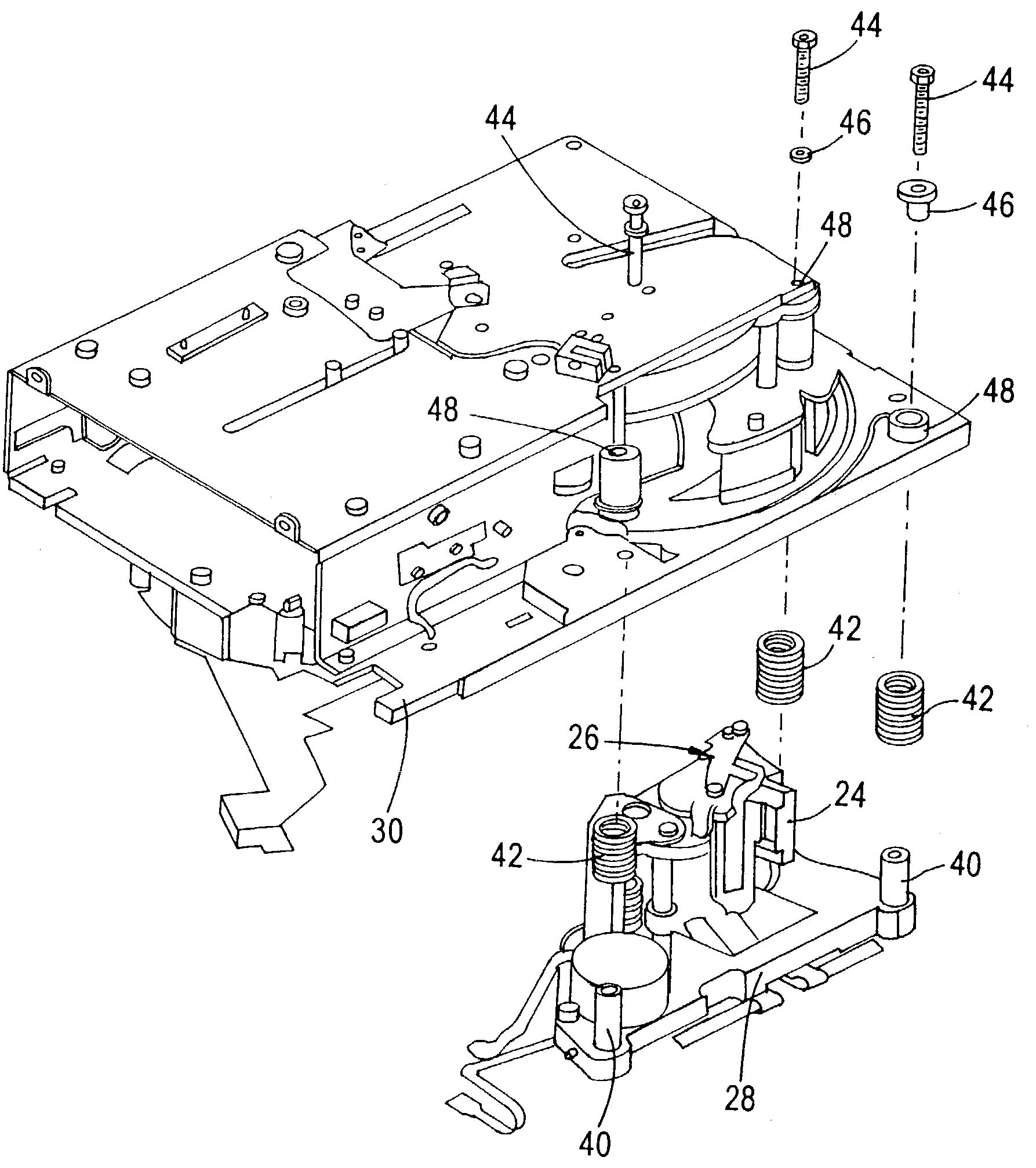
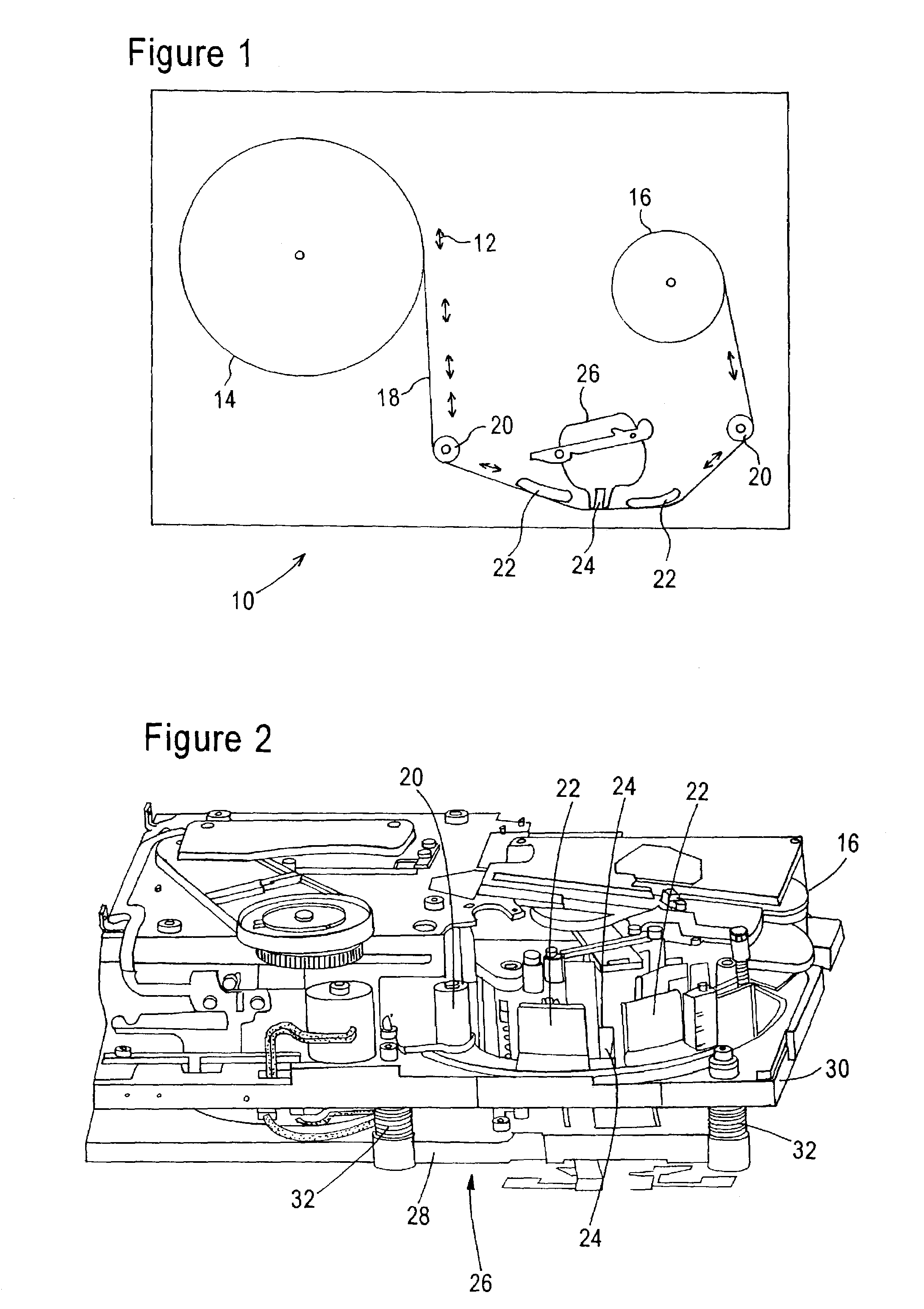
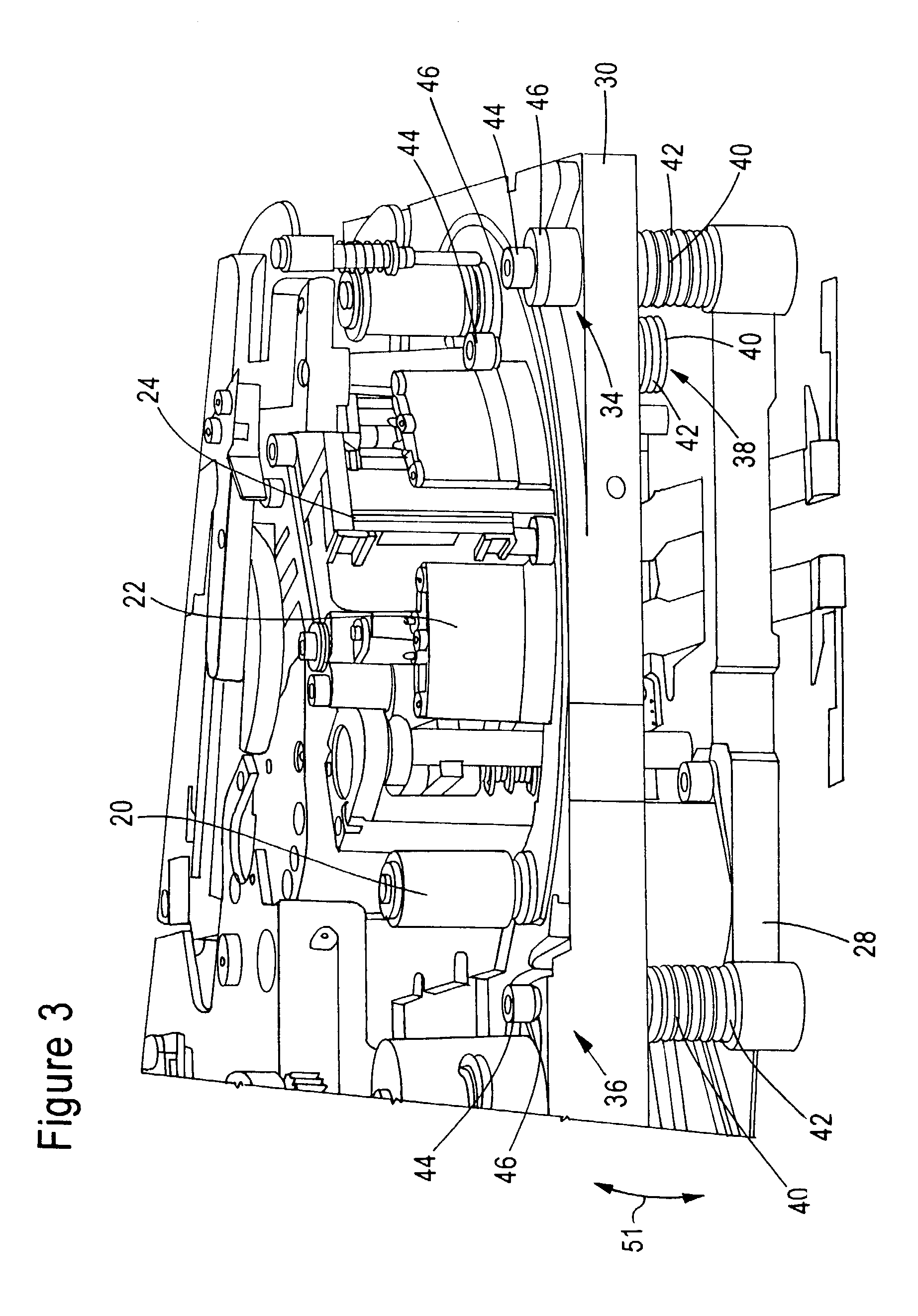
[0027]The present invention addresses and solves problems related to the head alignment apparatus and processes of conventional tape drive apparatus. These include aligning the head precisely in a controlled manner and maintaining the head alignment position in a procedure that does not require locking of any additional components. This is achieved, in part, by the present invention which provides a base plate that has tape path components on the base plate and a bracket that is adjustably coupled to the base plate. This bracket carries a magnetic head for reading and writing to a tape transported by a tape path component. The adjustment couplings couple the bracket to the base plate and are lockably settable to adjust and lock the spatial orientation of the magnetic head with respect to a tape transported by the tape path components. The adjustment couplings include upwardly extending posts on the bracket, with each post having a screwhole for receiving a screw. A spring concentric...


PUM

PropertyMeasurementUnit
angleaaaaaaaaaa
angleaaaaaaaaaa
angleaaaaaaaaaa

Abstract

A tape drive apparatus is provided with a base plate and tape path components on this base plate. The apparatus includes a bracket that is adjustably coupled to the base plate, the bracket carrying a magnetic head for reading and writing to a tape transported by the tape path components. Adjustment couplings couple the bracket to the base plate and are lockably settable to adjust and lock the spatial orientation of the magnetic head with respect to a tape transported by the tape path components. Pre-loaded jackscrews of the adjustment couplings are rotated to adjust and lock the azimuth and zenith settings for the magnetic head. A separate penetration screw independently controls the penetration of the magnetic head into the path of the magnetic tape.

Description

RELATED APPLICATIONS[0001]This application claims priority to provisional application Ser. No. 60 / 337,288, filed on Nov. 30, 2001.FIELD OF THE INVENTION[0002]The present invention relates to the field of tape drives, and more particularly, to systems for aligning the magnetic head of the tape drive apparatus.BACKGROUND OF THE INVENTION[0003]To perform an optimum magnetic recording on the tape drive apparatus, an accurate geometric relationship must be maintained between the path of the magnetic recording tape and the write-read gaps of the magnetic recording head. This geometric relationship is referred to as the “head alignment”. The head alignment includes the head-to-tape relationship in three main orientations. The “azimuth” relates to the perpendicularity of the head-gap with respect to the path of the tape. The “zenith” relates to the tilt of the head with respect to the tape. The “penetration” refers to the amount of penetration of the magnetic head into the path of the tape....

Claims


Application Information

Patent Timeline
Patent Type & Authority Patents(United States)
IPC IPC(8): G11B5/56G11B21/24
CPCG11B5/56G11B21/24
Inventor NAYAK, ASHOK B.
Owner QUANTUM CORP
Learn More