Fuel cell system
a fuel cell and system technology, applied in the field of fuel cell systems, can solve the problems of a long period of time, a large amount of time, and the inability to obtain power from the fuel cell assembly, and achieve the effect of enhancing the warm-up efficiency
- Summary
- Abstract
- Description
- Claims
- Application Information
AI Technical Summary
Benefits of technology
Problems solved by technology
Method used
Image
Examples
first embodiment
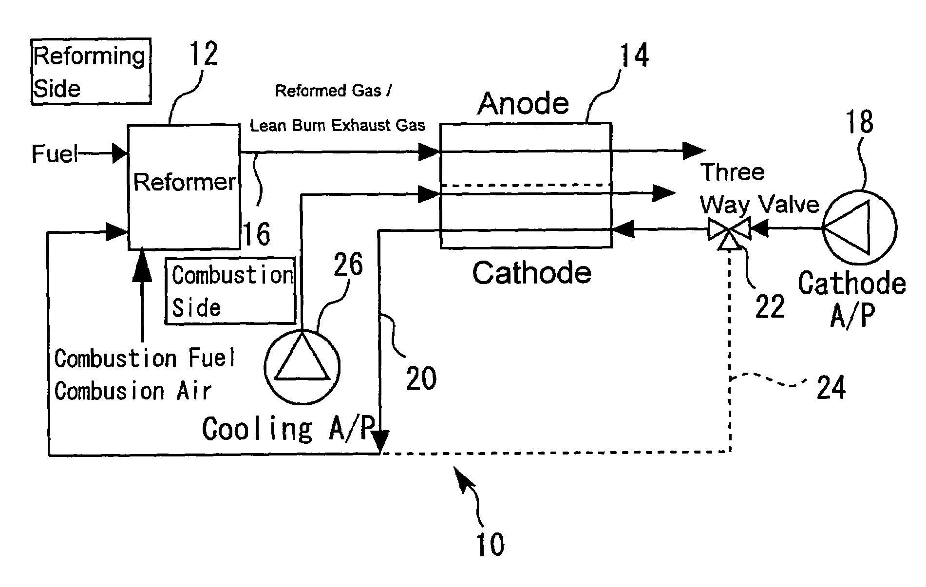
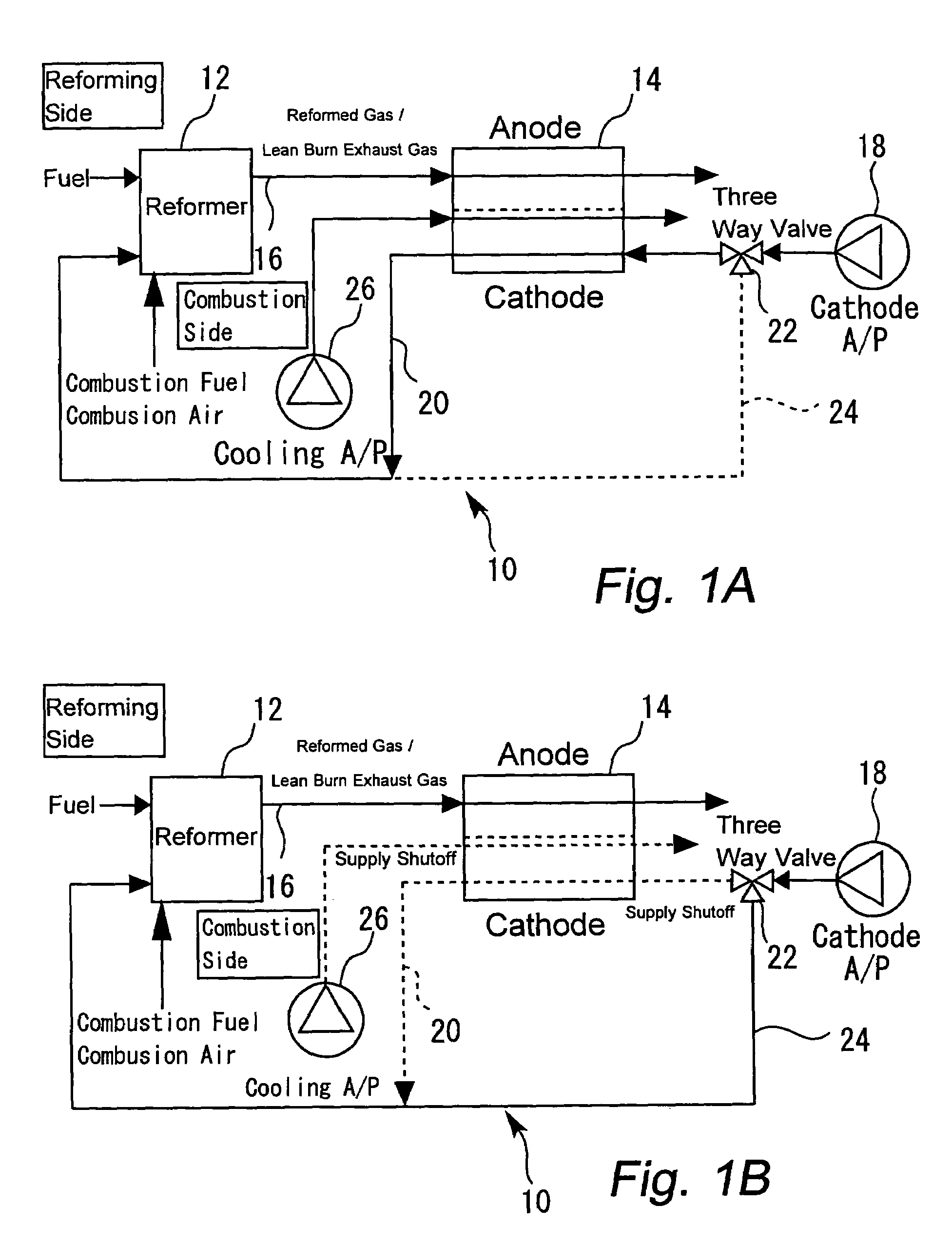
[0031]FIGS. 1A and 1B are schematic diagrams illustrating the configuration of a fuel cell system according to a first embodiment of the present invention. The fuel cell system 10 mainly includes an externally heatable, heat exchanger type reformer 12 and a fuel cell assembly 14. The reformer 12 uses hydrocarbon fuel, water, and air as materials to generate a hydrogen-rich fuel gas (reformed gas). The fuel cell assembly 14 generates power by using the reformed gas as fuel and air as oxidation gas.
[0032]The fuel cell assembly 14 is acceptable as far as it generates water (steam) at the time of power generation. More specifically, a proton exchange membrane fuel cell (PEM), phosphoric acid (PAFC), or hydrogen separation membrane fuel cell assembly may be used. If, for instance, the employed fuel cell assembly 14 is of a proton exchange membrane fuel cell, it comprises multi-layered cells, which each includes an electrolytic membrane, an anode, a cathode, and a separator. A fuel gas (r...
second embodiment
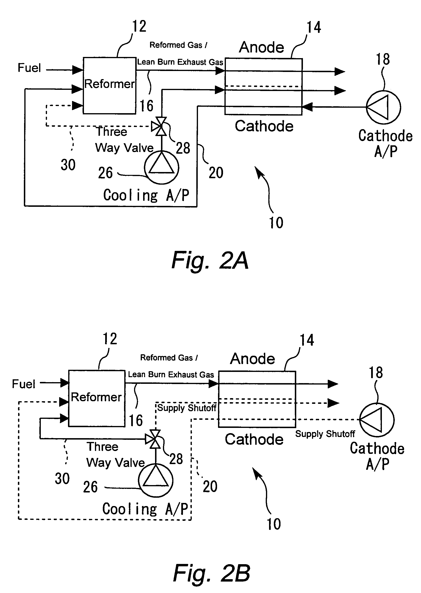
[0051]A second embodiment of the present invention will now be described. FIGS. 2A and 2B are schematic diagrams illustrating the configuration of a fuel cell system 10 according to the second embodiment. The basic configuration of the second embodiment of the fuel cell system 10 is the same as that of the first embodiment.
[0052]As is the case with the first embodiment, the second embodiment of the fuel cell system 10 includes the cathode off-gas flow path 20 for the purpose of supplying the cathode off-gas to the reforming side of the reformer 12. Further, the second embodiment also includes the cooling air pump 26 for the purpose of cooling the fuel cell assembly 14. In addition, the second embodiment includes a three-way valve 28, which is installed in a flow path for supplying the cooling gas to the fuel cell assembly 14. Another flow path 30 is furnished so that the cooling gas separated by the three-way valve 28 is forwarded to the reforming side of the reformer 12.
[0053]For a...
third embodiment
[0059]A third embodiment of the present invention will now be described. FIGS. 3A and 3B are schematic diagrams illustrating the configuration of a fuel cell system 10 according to the third embodiment of the present invention. The basic configuration of the third embodiment of the fuel cell system 10 is the same as that of the first embodiment.
[0060]As is the case with the first embodiment, the third embodiment of the fuel cell system 10 includes the cathode off-gas flow path 20 for the purpose of supplying the cathode off-gas to the reforming side of the reformer 12. Further, the third embodiment also includes the cooling air pump 26 for the purpose of cooling the fuel cell assembly 14. In addition, the third embodiment includes an air pump 32 for supplying air to the reforming side of the reformer 12 during warm-up.
[0061]For a normal operation, the cathode gas delivered from the cathode air pump 18 is forwarded to the cathode of the fuel cell assembly 14 as indicated in FIG. 3A. ...
PUM
| Property | Measurement | Unit |
|---|---|---|
| operating temperature | aaaaa | aaaaa |
| operating temperature | aaaaa | aaaaa |
| time | aaaaa | aaaaa |
Abstract
Description
Claims
Application Information
 - R&D
- Intellectual Property
- Life Sciences
- Materials
- Tech Scout
- Unparalleled Data Quality
- Higher Quality Content
- 60% Fewer Hallucinations
Browse by: Latest US Patents, China's latest patents, Technical Efficacy Thesaurus, Application Domain, Technology Topic, Popular Technical Reports.
© 2025 PatSnap. All rights reserved.Legal|Privacy policy|Modern Slavery Act Transparency Statement|Sitemap|About US| Contact US: help@patsnap.com


