Eureka AIR delivers breakthrough ideas for toughest innovation challenges, trusted by R&D personnel around the world.

Crop harvesting header with crop divider members carried on the reel

a technology of headers and crop dividers, which is applied in the direction of outside dividers, mowers, climate change adaptation, etc., can solve the problems of large equipment costs, difficult to separate the crop simply using the wire on the cone, and affecting the harvesting effect of crops,

Active Publication Date: 2006-11-07
MACDON INDS
View PDF9 Cites 37 Cited by
  • Summary
  • Abstract
  • Description
  • Claims
  • Application Information

AI Technical Summary

Benefits of technology

[0006]It is one object of the present invention to provide an improved harvester of the above general type in which there is provided an improved arrangement for separating cut crop from non-cut crop at the ends of the header.

Problems solved by technology

One problem which arises with crop harvesting headers of this type is that of separating the crop at the end of the header so that there is a clear separation between crop passing inwardly of the end of the header which goes to the knife and is therefore cut and must be separated from the crop which passes outwardly of the end of the header and therefore remains uncut.
Improper separation of the crop materials, particularly in crops which tend to entangle, can cause crops to be pulled into the knife at the end of the header so that blockages can occur in this location due to the inability of the knife to cut all of the crop which is pulled in from beyond the end of the header.
Some crops such as rice and various forage crops such as cane and sorghum provide a high level of entanglement so it is difficult to separate the crop simply using the wire on the cone.
These devices tend to be relatively expensive and require additional motors and mountings which can lead to additional complexity and therefore potential breakdown.

Method used


Image

  • Crop harvesting header with crop divider members carried on the reel
  • Crop harvesting header with crop divider members carried on the reel
  • Crop harvesting header with crop divider members carried on the reel

Examples


Embodiment Construction

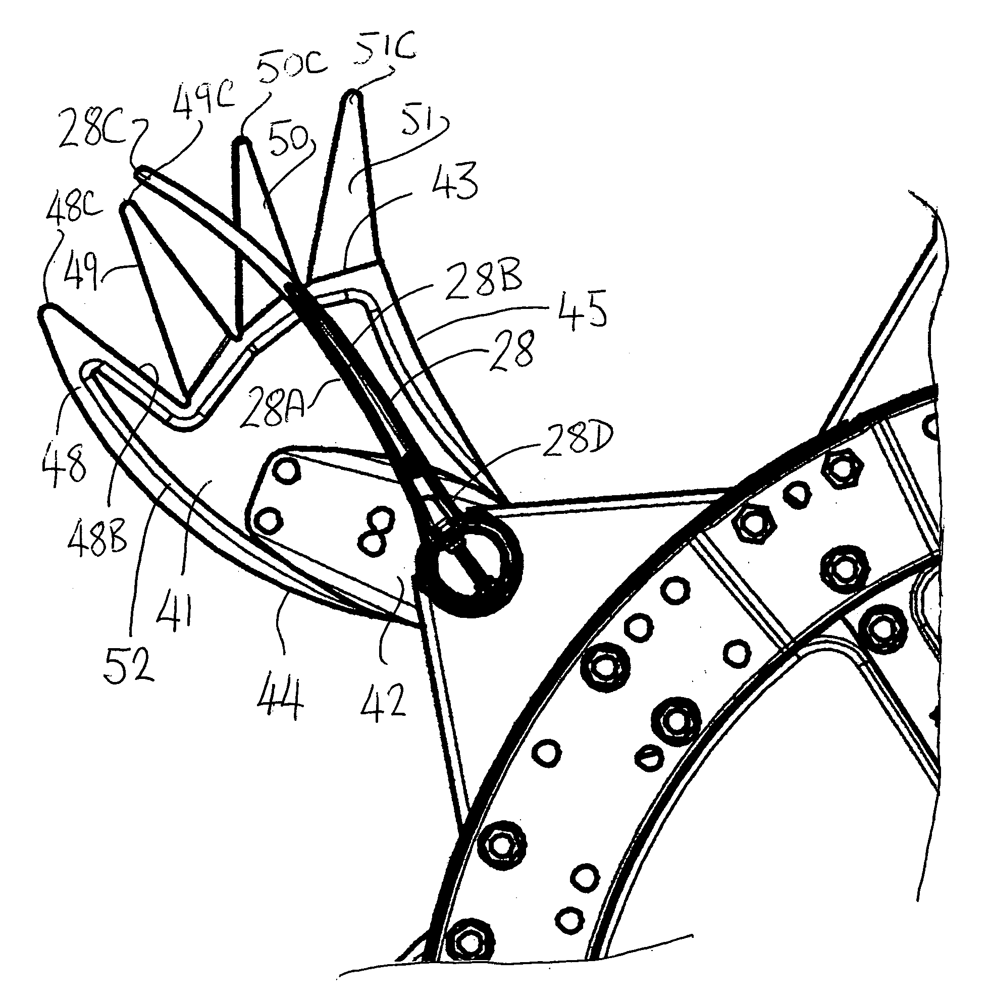
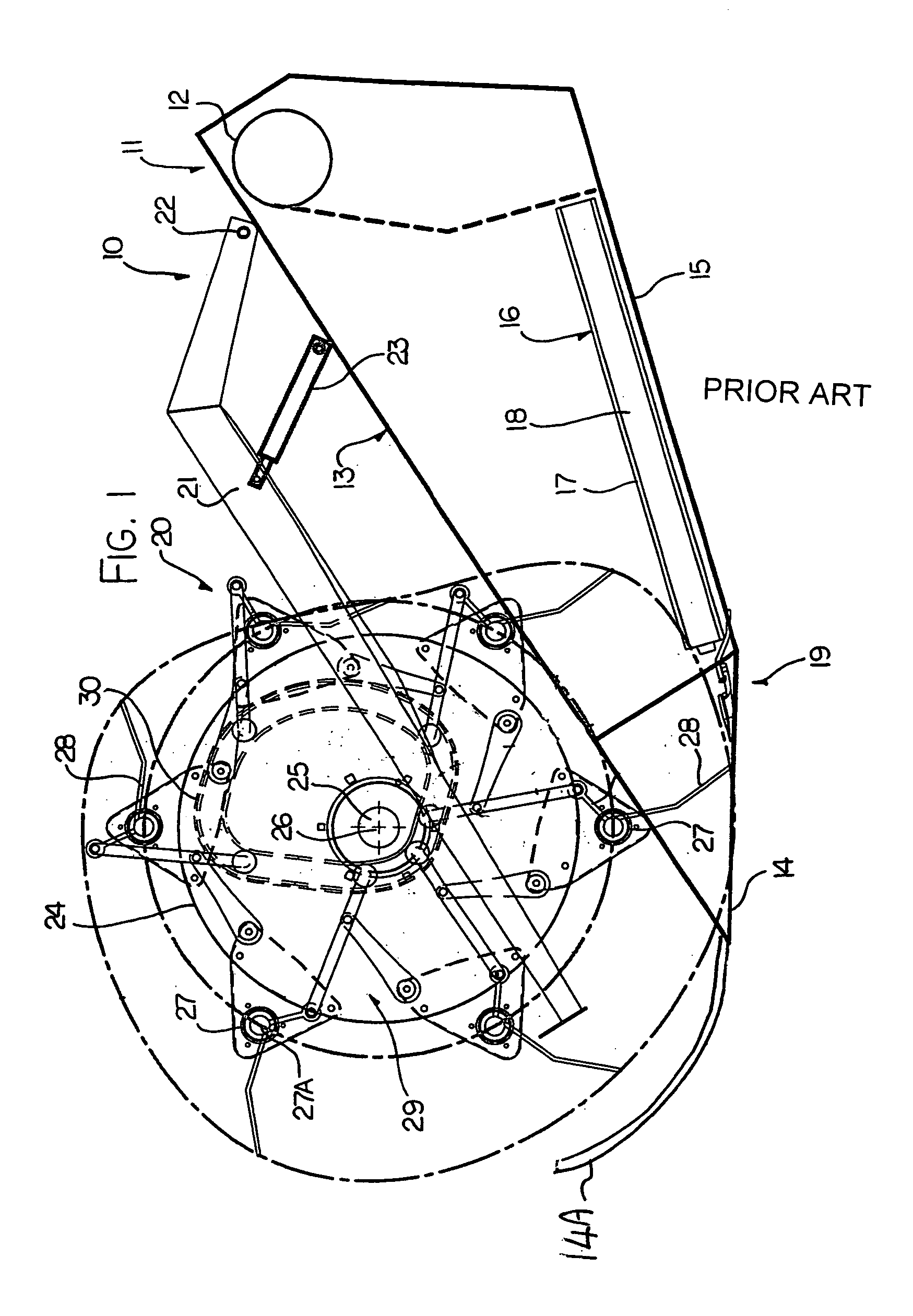
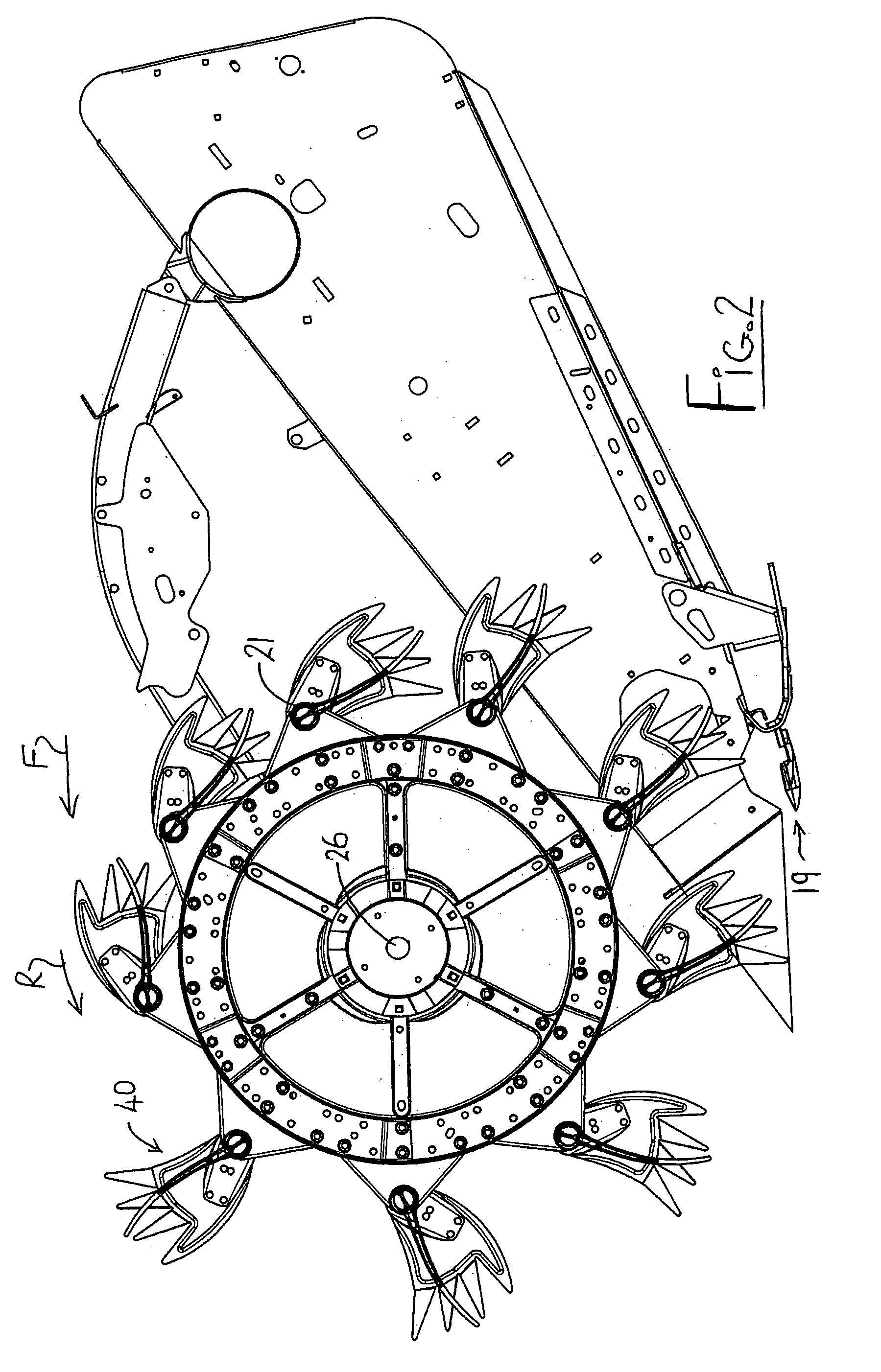
[0072]In FIGS. 1 and 5 is shown an embodiment of a header of the type with which the present invention is concerned with a number of the elements being shown schematically since the general construction of such headers is well known to one skilled in the art. The header 10 includes a header frame 11 having a main frame tube 12 extending across the width of the header between two end frames one of which is shown at 13 and the other of which is of course at the other end and therefore not visible in the elevation of FIG. 1. The main tube 12 is suitably supported and attached on a propulsion vehicle in a manner so that the header frame can be moved forwardly across the ground in cutting a standing crop. The end frame 13 extends forwardly from the main tube 12 to a forward nose section 14 which forms a divider so that crop to be cut passes on one side and crop which is to remain uncut and thus cut in a subsequent pass is separated and passes to the other side. A wire 14A is often provid...


PUM


Abstract

A crop harvesting header includes a cutter bar arranged across a forward edge, a draper or auger transport arrangement for transporting the cut crop, and a reel mounted on reel arms having a plurality of reel bats at spaced positions around the reel axis each reel bat having reel fingers projecting generally radially outwardly from the reel axis. Each bat is mounted for pivotal movement about its bat axis. At both ends of each bat is mounted a crop divider which pivots with the bat and is formed with a plate lying in a radial plane of the bat with angularly spaced fingers around the outer edge. A leading edge of the plate and front finger is convexly curved relative to the concave curve of the front edge of the finger and is angularly advanced relative to the leading edge of the adjacent fingers such that the rotating crop dividers on the reel co-operate with a stationary crop on the header to separate the cut crop from uncut crop passing alongside the end of the header.

Description

[0001]This invention relates to a crop harvesting header including a cutter bar and a reel for controlling movement of the crop in the area over the cutter bar in which the reel is rotatable about an axis generally parallel to the cutter bar and has a plurality of reel bats each having reel fingers projecting generally radially outwardly from the reel axis and particularly to an arrangement for improving crop separation between cut and uncut crop at the end of the header.BACKGROUND OF THE INVENTION[0002]One problem which arises with crop harvesting headers of this type is that of separating the crop at the end of the header so that there is a clear separation between crop passing inwardly of the end of the header which goes to the knife and is therefore cut and must be separated from the crop which passes outwardly of the end of the header and therefore remains uncut. Improper separation of the crop materials, particularly in crops which tend to entangle, can cause crops to be pulle...

Claims


Application Information

Patent Timeline
Patent Type & Authority Patents(United States)
IPC IPC(8): A01D34/00
CPCA01D57/02A01D63/02Y02A40/28
Inventor REMILLARD, RHEAL G.VAN LIERE, ABRAHAM JACOB
Owner MACDON INDS
Why Eureka
Eureka Blog
Learn More