Container closure

Inactive Publication Date: 2006-10-31
ADVANCED BIOTECHNOLOGIES LTD
View PDF16 Cites 13 Cited by
  • Summary
  • Abstract
  • Description
  • Claims
  • Application Information

AI Technical Summary

Benefits of technology

[0008]According to a first aspect of the present invention there is provided a closure means adapted to fit into the neck or mouth of a container, said closure means comprising a plug of resilient material said plug incorporating a slit which extends through the body of the plug characterised in that, in a resting configuration and prior to insertion of the closure means into a container, the breadth of the slit is non-uniform along the length of the slit. By providing a slit of non-uniform breadth the force exerted on a pipette or needle inserted through the closure can be controlled whilst still retaining a good fluid tight seal under normal conditions.

Problems solved by technology

Once applied, these films provide an efficient, gas and liquid-tight seal but are tiresome to apply and remove.
Access to each well can only be obtained by piercing the film or by peeling off the film by hand or with a foil stripper.
Consequently, this type of seal is not reusable, and is not suitable for robotic application or removal.
Furthermore, the seal does not reform automatically if a sample is withdrawn with a syringe needle, pipette tip or cannula for example.
However, such mats do not produce a complete, fluid-tight seal and some evaporation can still take place.
However, each time a needle is inserted through the cap it causes some damage to the septum region as it punctures the surface.
Eventually, after a number of such penetrations, the damaged area no longer forms a fluid-tight seal.
These two requirements tend to be mutually incompatible.
This problem is compounded if multiple samples (multi-sipping) are required.

Method used


Image

  • Container closure
  • Container closure
  • Container closure

Examples


Embodiment Construction

[0043]The invention will now be described by way of example only. These examples represent the best ways known to the applicant of putting the invention into practice, but they are not the only ways in which this can be achieved.

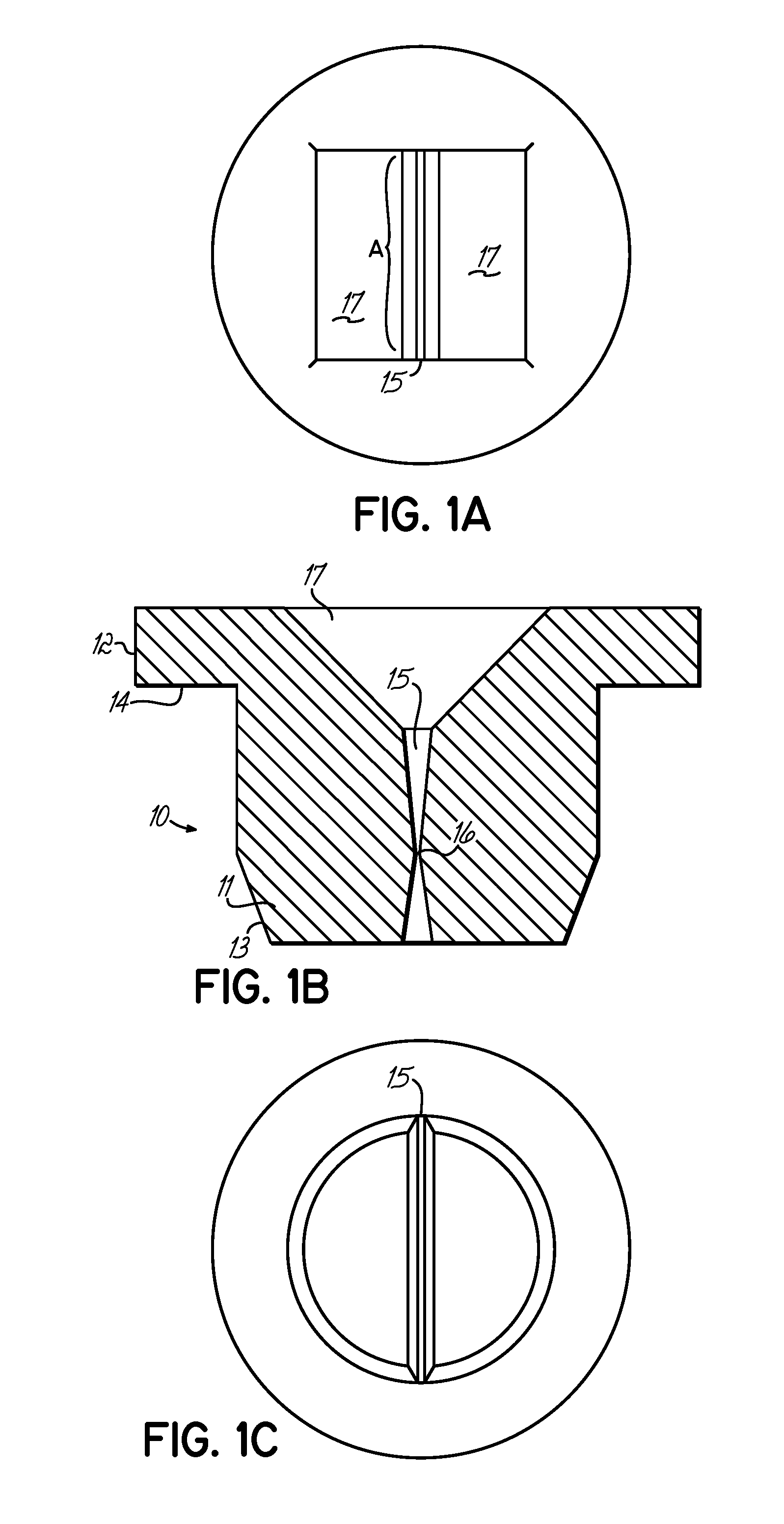
[0044]Referring to FIG. 1, this illustrates a closure means 10 formed from a plug of resilient material and consisting of a lower cylindrical portion 11 and an upper cylindrical portion 12. The lower cylindrical portion has a diameter slightly larger than that of the tube in which it is intended to fit. The lower end portion 13 or bottom perimeter of the lower cylindrical portion 11 is slightly chamfered to ensure an easy fit into the tube. The upper cylindrical portion 12 has a diameter that is larger than that of the tube such that it overlies the tube wall (not shown) when the closure means is pushed fully home. In use, the tube wall abuts shoulder 14.

[0045]In the present example the resilient plug is of unitary construction and is formed from an elastome...


PUM


Abstract

A closure means adapted to fit into the neck or mouth of a container, said closure means comprising a plug of resilient material said plug incorporating a slit which extends through the body of the plug characterized that, in a resting configuration and prior to insertion of the closure means into a container, the breadth of the slit is non-uniform along the length of the slit.

Description

FIELD OF THE INVENTION[0001]The present invention relates to closure means for tubes, multi-well plates or other containers. It is particularly applicable, but in no way limited, to multi-sipping caps and tubes or containers incorporating multi-sipping caps.BACKGROUND TO THE INVENTION[0002]In life science chemistry, for example, there are a wide number of applications that involve preparation, storage and analysis of a large number of samples. Such applications include drug discovery, including combinatorial chemistry, and Polymerase Chain Reaction (PCR) experiments. In these applications reaction tubes, vials or the like are often filled or part filled with reagents and the tubes sealed prior to further processing. In addition, multi-well plates, consisting of an array of tubes, are now used extensively in molecular biology laboratories and elsewhere.[0003]A number of ways for sealing such tubes have been developed over the years. For example, a foil or plastic film may be applied ...

Claims


Application Information

Patent Timeline
IPC IPC(8): B65D39/00B01L3/14B65D51/00
CPCB01L3/50825B65D51/002
Inventor COLLINS, PETER ANTHONY
Owner ADVANCED BIOTECHNOLOGIES LTD
Why Eureka
Try Eureka