
System and method to autonomously and selectively jam frequency hopping signals in near real-time

a frequency hopping radio and autonomous technology, applied in multi-frequency code systems, duplex signal operation, instruments, etc., can solve the problems of difficult to selectively jam frequency hopping radios using today's normal methods, difficult to conduct successful electronic attacks against proliferating radios, and increasing difficulty in detecting and detecting the signal in real tim

Inactive Publication Date: 2006-10-24
AGILENT TECH INC
View PDF6 Cites 23 Cited by
  • Summary
  • Abstract
  • Description
  • Claims
  • Application Information

AI Technical Summary

Benefits of technology

[0016]The preferred system should first have the ability to automatically detect short duration signals (such as those output from frequency hoppers). Secondly the preferred system should be able to automatically make a determination if a received signal should be jammed. Thirdly, the preferred system should then automatically and extremely quickly activate the jamming transmitter on the hoppers' frequencies. And finally, the preferred system should provide a programmable interface so that operators can set up the system to act autonomously as intended, so there is no operator intervention necessary when the preferred system goes into the jamming mode of operations.

Problems solved by technology

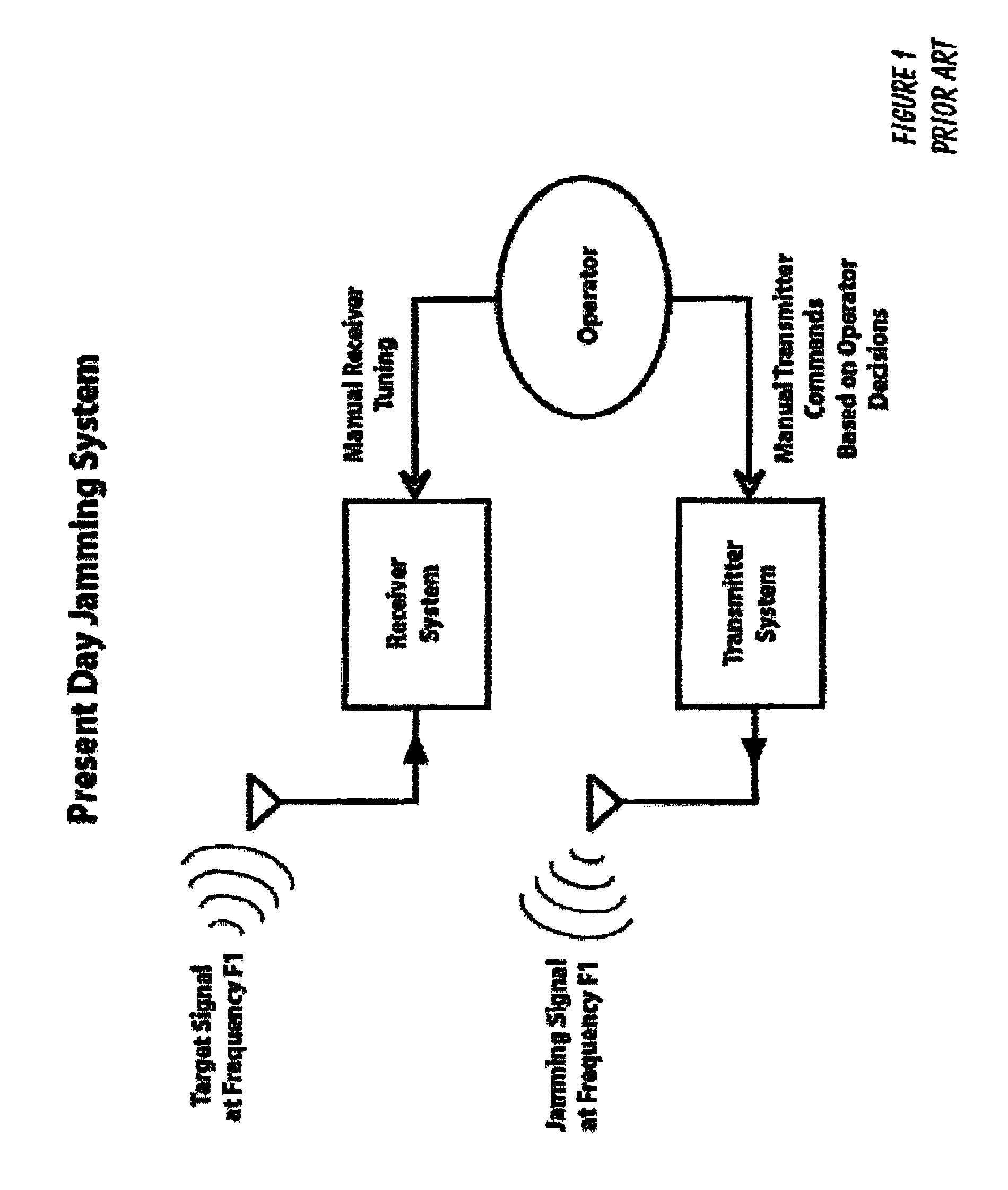
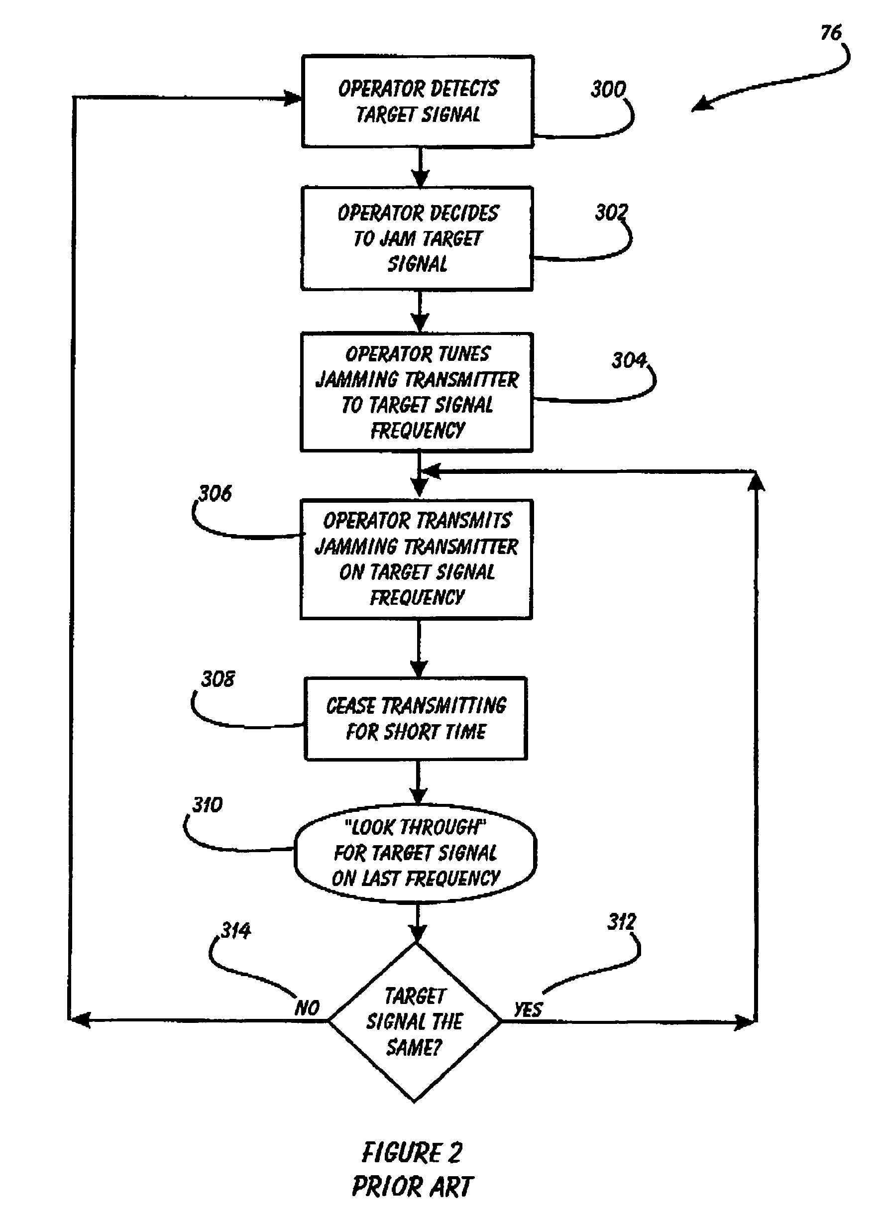
Today's modem military grade frequency hopping radios present many problems for those who want to detect and jam such transmitters.
The short duration nature of frequency hoppers makes it practically impossible to selectively jam them using today's normal methods.
It is getting increasingly difficult to conduct successful electronic attacks against these proliferating, jam resistant targets with legacy equipment and technology.
Such a system cannot rely on prior art methods of using standard CPU driven technology.

Method used


Image

  • System and method to autonomously and selectively jam frequency hopping signals in near real-time
  • System and method to autonomously and selectively jam frequency hopping signals in near real-time
  • System and method to autonomously and selectively jam frequency hopping signals in near real-time

Examples


Embodiment Construction

[0023]The following description is provided to enable any person skilled in the art to make and use the invention and sets forth the best modes contemplated by the inventor of carrying out his invention. Various modifications, however, will remain readily apparent to those skilled in the art, since the generic principles of the present invention have been defined herein specifically to provide a System and Method to Autonomously and Selectively Jam Frequency Hopping Signals in Near Real-time.

[0024]The present invention can best be understood by initial consideration of FIG. 4. FIG. 4 is a functional depiction of a preferred embodiment of the present invention, a near real-time frequency hopper jamming system. Once armed for jamming, the system first receives and instantaneously processes a wide bandwidth of RF spectrum. The invention will then detect short duration signals such as frequency hopping signals and burst transmissions. Such suddenly appearing signals are then automatical...


PUM


Abstract

The system and method autonomously and selectively jams frequency-hopping signals in near real-time by incorporating a fundamental change in the detection and reaction technology, to provide a reaction time that is short enough, within milliseconds or less, to capture and then jam even the fastest frequency hopping radios in use today, without relying on prior art methods of using standard CPU driven technology.The system automatically determines if detected signal(s) should be jammed, and subsequently to automatically end extremely quickly activates the jamming transmitter on the frequency-hopper transmitter's frequency. Finally, the system provides a programmable user interface so that operators can set up the system to act autonomously as intended, such that operator intervention is unnecessary when the system is placed in jamming operation mode.

Description

[0001]This application is a continuation-in-part of application Ser. No. 10 / 829,858, filed Apr. 21, 2004, now pending.[0002]This application is filed within one year of, and claims priority to Provisional Application Ser. No. 60 / 495,831, filed Aug. 18, 2003.BACKGROUND OF THE INVENTION[0003]1. Field of the Invention[0004]This invention relates to advanced military grade communications jamming systems and, more specifically, to a System and Method to Autonomously and Selectively Jam Frequency Hopping Signals in Near Real-time. This unique state-of-the-art invention will have widespread use in any modem military organization that wants to achieve communications dominance and information superiority over any battlefield. The invention will add an essential, and much needed, communications and electronic warfare capability to any respective governments' national defense program.[0005]2. Description of Related Art[0006]Modem military grade communication systems today employ short, burst t...

Claims


Application Information

Patent Timeline
Patent Type & Authority Patents(United States)
IPC IPC(8): H04B1/69H04K1/10H04K3/00
CPCH04K3/42H04K3/45H04K3/68
Inventor KARLSSON, LARS
Owner AGILENT TECH INC
Learn More