
Serially connected LED lamps control device

a technology of led lamps and control circuits, applied in recording devices, instruments, printing, etc., can solve the problems of high cost of electric cables, difficult mass production and installation, and low cost of such methods, and achieve the effects of enhancing overall system stability, extending the distance between a plurality of serially connected devices, and increasing data and clock lines

Inactive Publication Date: 2006-10-24
STAR REACH
View PDF3 Cites 2 Cited by
  • Summary
  • Abstract
  • Description
  • Claims
  • Application Information

AI Technical Summary

Benefits of technology

[0010]Therefore, the primary objective of the present invention is to provide a serially connected LED lamps control circuit device, which is applicable for an integrated circuit and has the following three features: using a buffer circuit to increase the DATA and Clock lines to extend the distance between a plurality of serially connected devices, delaying the half cycle of the timing of the DATA line to enhance overall system stability, and adding an internal latch signal generated circuit to simplify the requirements for external connections.

Problems solved by technology

The cost for such method is lower; however, if the lamps are farther apart from each other or evenly distributed or arranged, then the cost of the electric cable is very high.
Furthermore, since the length for each cable is not the same, which will cause tremendous difficulty for mass production and installation.
Therefore, this design was adopted only at its early stage, but is seldom used thereafter because of its disadvantages.
Since each lamp requires a controller, therefore the cost is higher.
In addition, each lamp requires a different ID, and thus making the manufacturing more difficult.
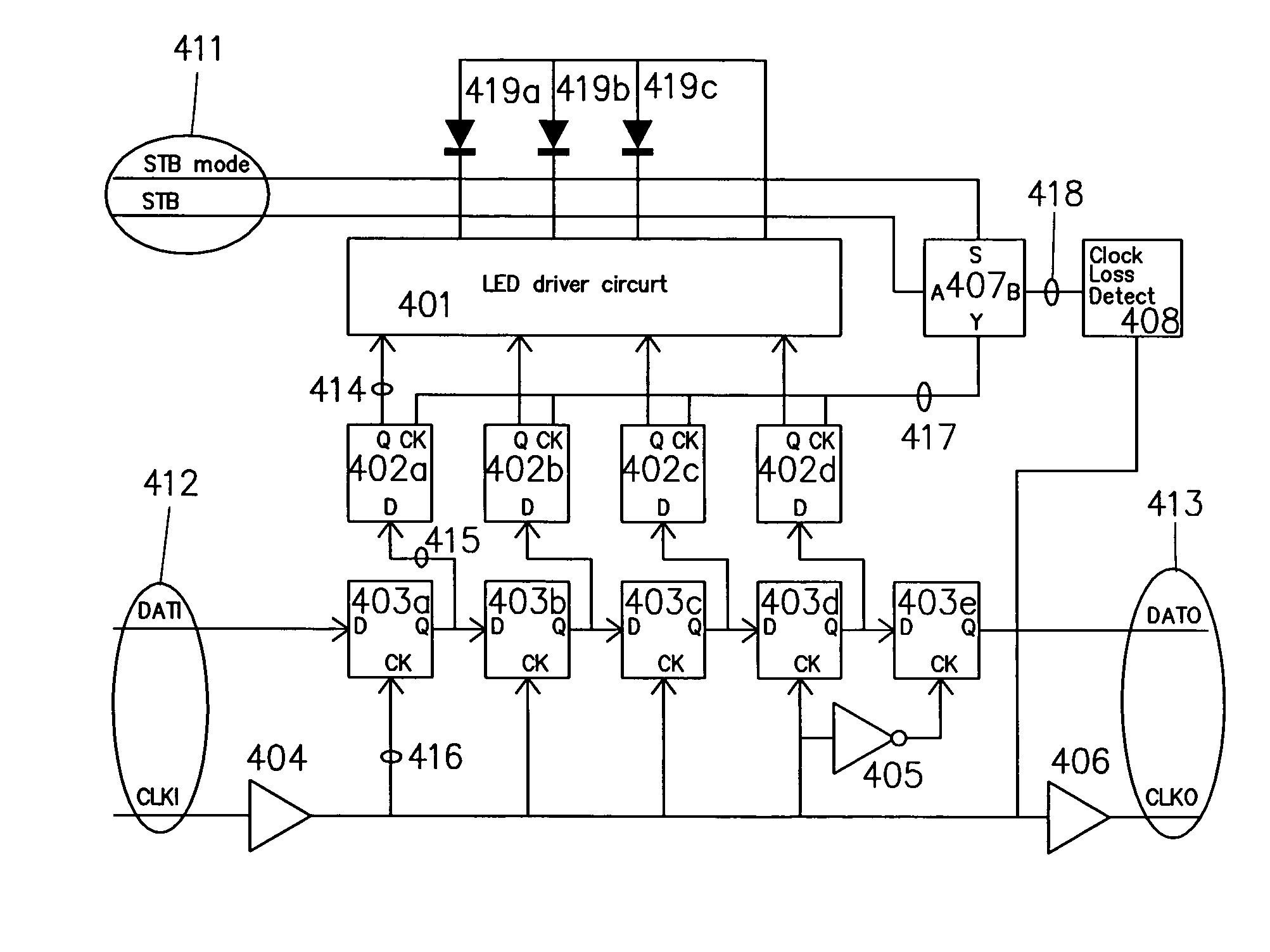
Furthermore, it is necessary to change the ID of the spare parts for repair and maintenance purposes, thus causing some troubles.

Method used


Image

  • Serially connected LED lamps control device
  • Serially connected LED lamps control device
  • Serially connected LED lamps control device

Examples


Embodiment Construction

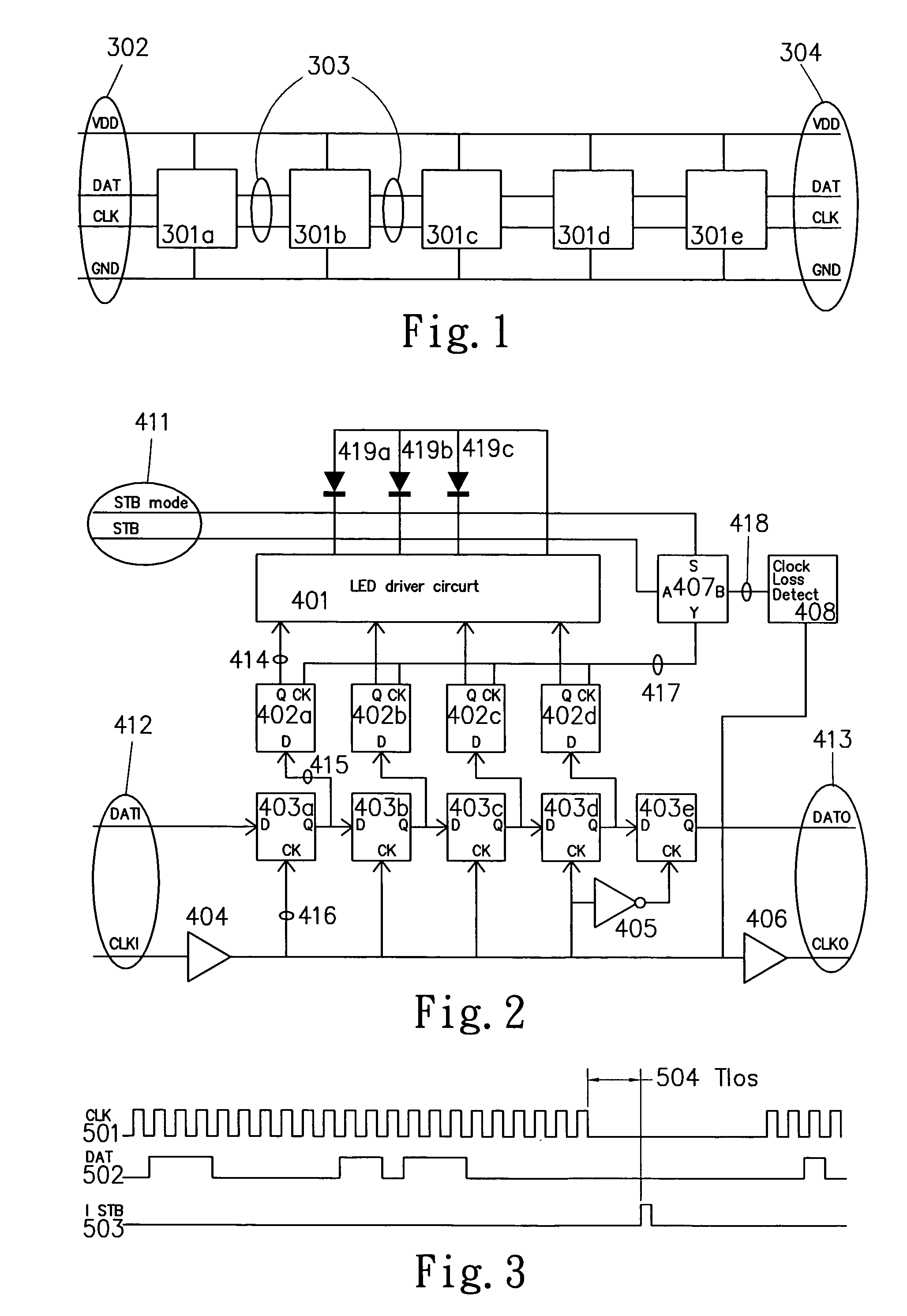
[0019]Please refer to FIG. 1 for the block diagram of the method for connecting the LEDs according to the present invention. In FIG. 1, the whole circuit device only requires two signal lines: CLK and DAT in addition to the power supply VDD and ground GND. There are five lamp units 301a˜301e, an input end 302, and an output end 303. The device is very simple and neat, which consists only four circuits between all lamps.

[0020]FIG. 2 illustrates the structure of the present invention. There are two differences from the traditional structure as depicted in FIG. 8, such as a D-type latch 403e is installed in front of the data output DATO for the inverted clock synchronization, which can delay the data for half a cycle; and a clock loss detect circuit 408 is added. If a data DATI and the clock 502 as shown in FIG. 3 are sent, the clock CLKI and the clock 501 as shown in FIG. 3 will stop for a while, and then TIos 504 as shown in FIG. 3 and the circuit 408 will automatically generate a la...


PUM


Abstract

The present invention discloses a serially connected LED lamps control circuit device, which is applicable for an integrated circuit and has the following three features: using a buffer circuit to increase the DATA and Clock lines to extend the distance between a plurality of serially connected devices, delaying half cycle of the timing of the DATA line to enhance overall system stability, and adding an internal latch signal generate circuit to simplify the requirements for external connections.

Description

FIELD OF THE INVENTION[0001]The present invention relates to a serially connected LED lamps control circuit device, which is applicable for an integrated circuit and characterized in its using a buffer circuit to increase the DATA and Clock lines to extend the distance between a plurality of serially connected devices, delaying the half cycle of the timing of the DATA line to enhance overall system stability, and adding an internal latch signal generated circuit to simplify the requirements for external connections.BACKGROUND OF THE INVENTION[0002]The application of LED becomes popular, and the progress of LED brightness also promotes an extensive use of LEDs. Based on years of experience on research, development and selling of the LED products, the inventor of the present invention has developed a control device for improving system stability as well as greatly simplifying the system wiring.[0003]The design of serially connected LED lamp control device is mainly applied for the occ...

Claims


Application Information

Patent Timeline
Patent Type & Authority Patents(United States)
IPC IPC(8): H04N1/407
CPCH05B33/0842H05B45/30
Inventor YEN, GEORGE
Owner STAR REACH
Learn More