
Liquid crystal display of line-on-glass type having voltage difference compensating means

a liquid crystal display and voltage difference technology, applied in the field of line-on-glass liquid crystal displays, can solve the problems of deteriorating the picture quality of the liquid crystal display, difficult to achieve compensation solutions, and difficulty in confined spaces, so as to achieve uniform brightness

Active Publication Date: 2006-10-17
LG DISPLAY CO LTD
View PDF7 Cites 17 Cited by
  • Summary
  • Abstract
  • Description
  • Claims
  • Application Information

AI Technical Summary

Benefits of technology

The present invention provides a liquid crystal display that compensates for voltage differences between gate driver ICs caused by variations in signal transmission lines. This results in a uniform brightness across horizontal line blocks on the display. The invention includes a voltage difference compensating means that includes a resistor connected to the gate driver integrated circuits to compensate for a voltage difference between the driving signals. This ensures that the display is consistent and of high quality.

Problems solved by technology

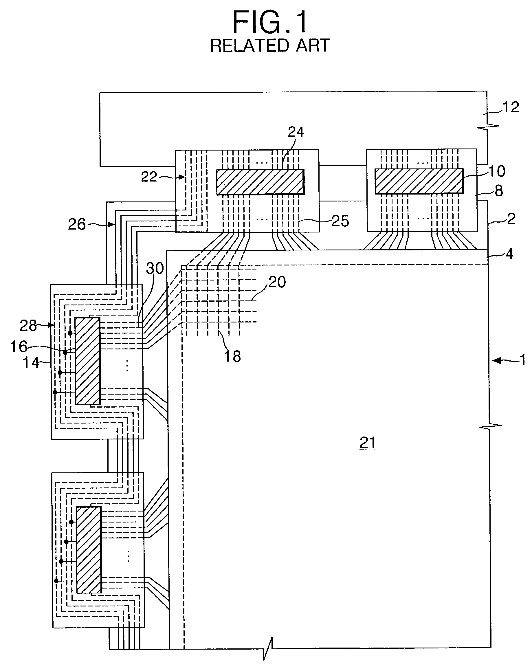
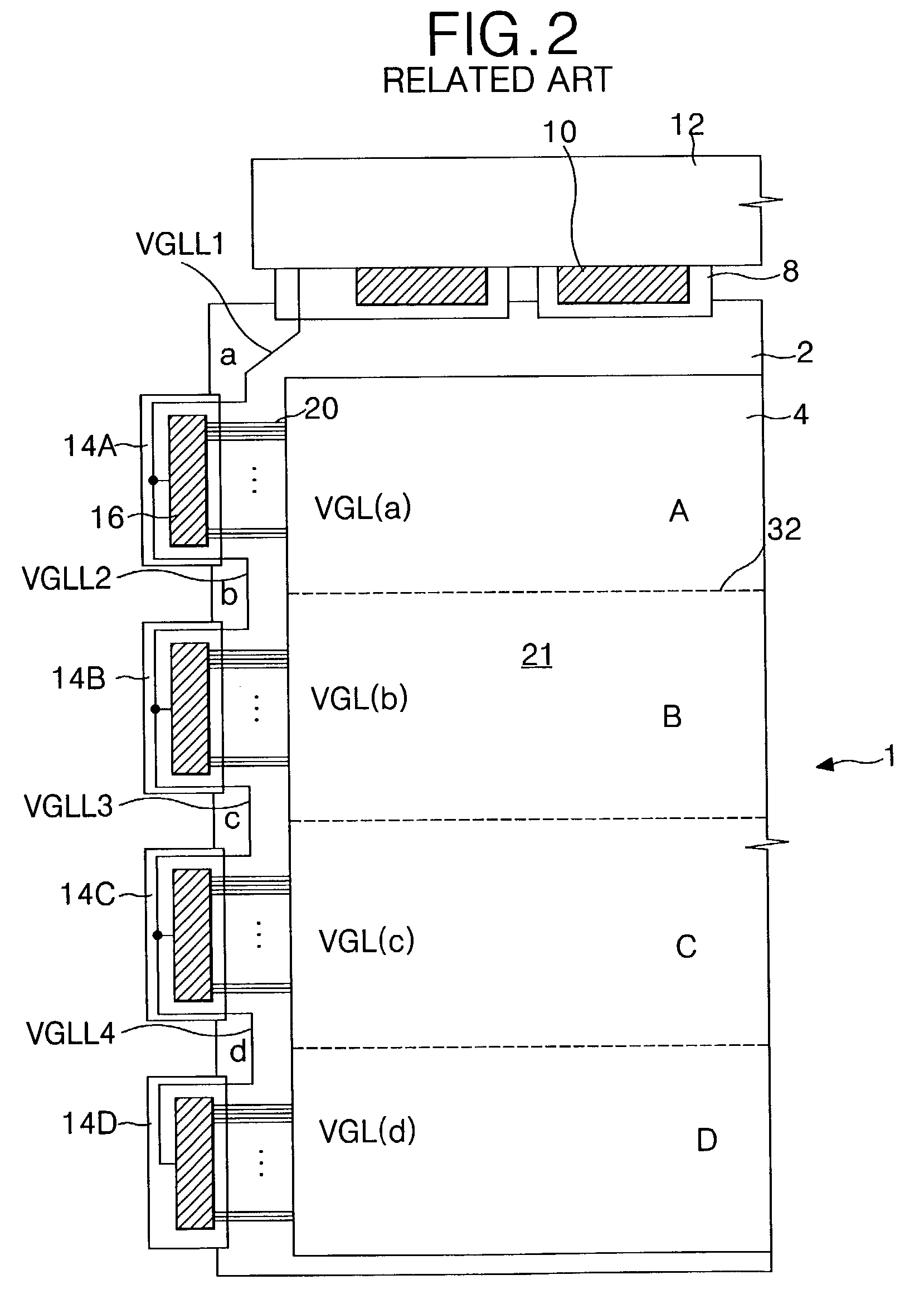
The technical problem addressed in this patent text is the non-uniform brightness of images displayed on a liquid crystal display caused by differences in resistance values between the gate low voltage signals and the design of the logic signal line group. The resistance values of the signal transmission lines within the logic signal line group are proportional to their lengths and can affect the picture quality of the display. Current solutions to compens for these differences are difficult to achieve and can result in a cross-line phenomenon that divides the screen in brightness values.

Method used


Image

  • Liquid crystal display of line-on-glass type having voltage difference compensating means
  • Liquid crystal display of line-on-glass type having voltage difference compensating means
  • Liquid crystal display of line-on-glass type having voltage difference compensating means

Examples


Embodiment Construction

[0047]Reference will now be made in detail to embodiments of the present invention, examples of which are illustrated in the accompanying drawings.

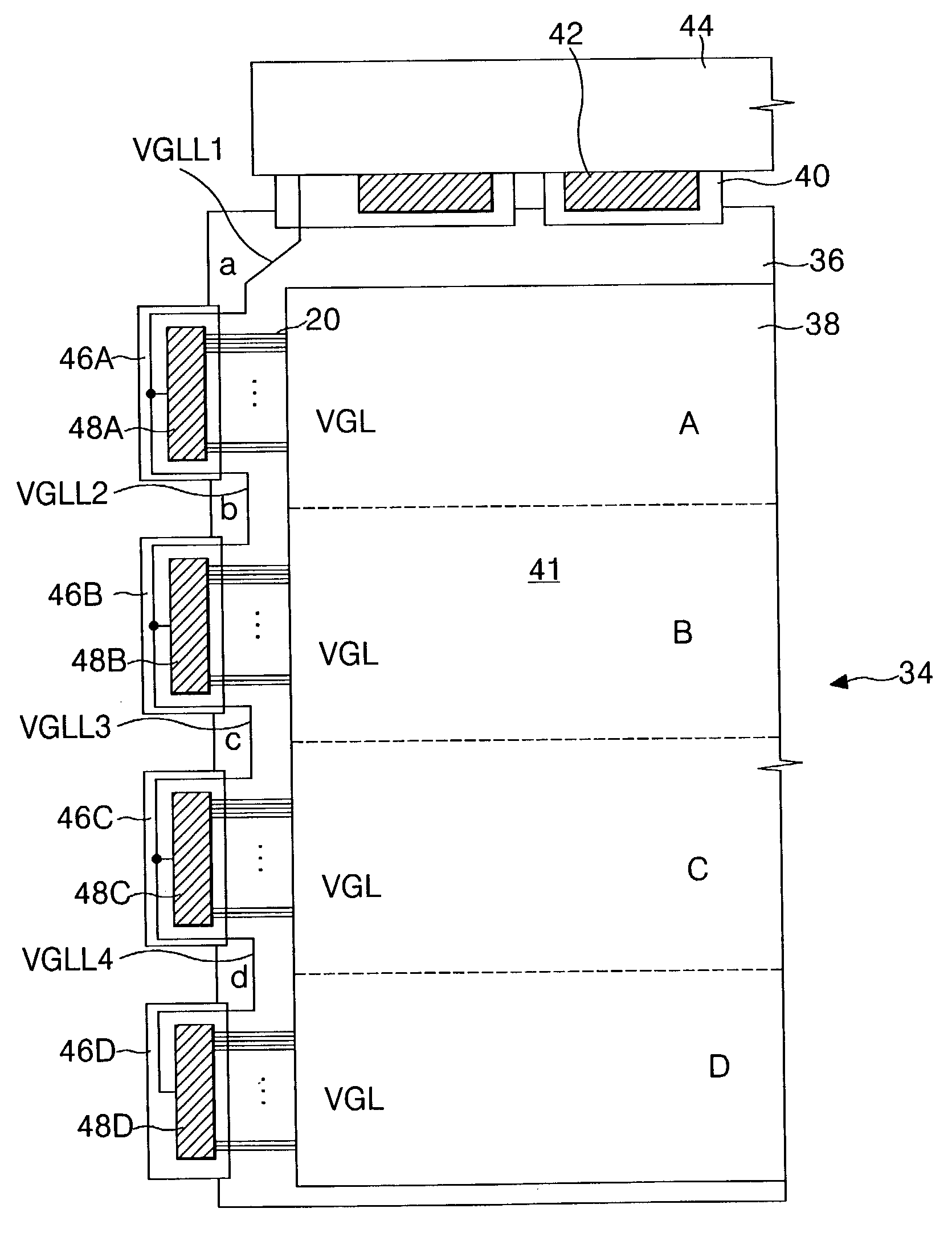
[0048]FIG. 3 illustrates a schematic view of a line-on-glass liquid crystal display according to one aspect of the present invention.

[0049]Referring to FIG. 3, the liquid crystal display according to the principles of the present invention may, for example, include a liquid crystal display panel 34, a plurality of data TCPs 40 connected between a first side of the liquid crystal display panel 34 and a data PCB 44, first to fourth gate TCPs 46A to 46D connected to a second side of the liquid crystal display panel 34, a plurality of data driver ICs 42 mounted on the data TCPs 40, and first to fourth gate driver ICs 48A to 48D mounted on the first to fourth gate TCPs 46A to 46D, respectively. In one aspect of the present invention, an input terminal of each of the gate driver ICs 48A to 48D may be provided with a compensating means for compe...


PUM


Abstract

A LOG-type liquid crystal display device includes a picture display area having liquid crystal cells arranged at crossings of gate lines and data lines, gate driver integrated circuits for driving the gate lines are mounted on gate tape carrier packages, data driver integrated circuits for driving the data lines are mounted on data tape carrier packages, line-on-glass type signal lines arranged at an outer portion of the picture display area for applying driving signals to the gate drive integrated circuits. A voltage difference compensating means is connected to each of the gate driver integrated circuits to compensate for voltage differences between the driving signals according to line resistance differences between the line-on-glass type signal lines.

Description


Claims


Application Information

Patent Timeline
Owner LG DISPLAY CO LTD
Learn More